• Steel Soldiers now has a few new forums, read more about it at: New Munitions Forums!

  • Microsoft MSN, Live, Hotmail, Outlook email users may not be receiving emails. We are working to resolve this issue. Please add support@steelsoldiers.com to your trusted contacts.

Troubleshooting Horn

Speddmon

Blind squirrel rehabiltator
Super Moderator
Steel Soldiers Supporter
4,640
28
38
Location
Cambridge, Ohio
I don't think you guys are talking about the same part.

Tinwoodsman said the solenoid he was talking about was "The two terminal solenoid I found was on the engine side of the firewall just below the main harness feed from the cabin". Which I don't think is a solenoid at all but the circuit breaker. IIRC, the horn solenoid is mounted dierctly on the horn! That is the solenoid DH is talking about.
 

Tinwoodsman

Well-known member
Steel Soldiers Supporter
3,923
75
48
Location
Comfort, Texas
At this point, I am not sure I know a solenoid from a circuit breaker. Anyway, continuity on the C/B is correct and there is no continuity on the solenoid so I will order one tomorrow and, hopefully, all will be good. Thanks to all for the help.
 

Amram

New member
245
0
0
Location
Bremerton, Washington
DH, my horn soleniod activates when I push the button even with the ignition switch off on my truck. Is this correct for all trucks or is mine messed up? It is a known fact I have been having wiring harness issues with cracked/ dry rotted insulation. I just got my horn working this weekend. It came down to a faulty button and a severed ground wire that plugs into the column wire.
 

Flyingvan911

Well-known member
4,709
158
63
Location
Kansas City, MO
My horn also blows with the accessory switch off. It looks like it is the OEM set up. It's fun for unsuspecting people. It's also nice because little kids can blow it without me having to start the truck each time.
 

doghead

4 Star General /Moderator
Staff member
Super Moderator
Steel Soldiers Supporter
26,247
1,168
113
Location
NY
I just edited my previous post(#11). The horn does have power all the time, it is supplied by wire number 10(before the ignition switch).
 

Tinwoodsman

Well-known member
Steel Soldiers Supporter
3,923
75
48
Location
Comfort, Texas
So, if I am reading the schematic correctly, #10 wire runs from the magnetic relay at the starter, to the horn circuit breaker and then runs to the horn relay via #25 wire.
 

Tinwoodsman

Well-known member
Steel Soldiers Supporter
3,923
75
48
Location
Comfort, Texas
I am still trouble shooting my horn circuit. As said before, I get 24 volts (constant) at on one of the wires connected to the solenoid. Based on the wiring diagram, that must be the one coming from the circuit breaker. Logic tells me I should also be getting the same voltage on one of the circuit breaker terminal that goes to the #25 lead. Is that correct?
 

steelandcanvas

Well-known member
6,187
85
48
Location
Southwestern Idaho
Just grabbin' at straws here, after doing your horn kit, did you re-make the connection at the bottom of the steering column? That would be your ground to your horn solenoid. Also, using your meter, test continuity from chassis ground to the wire that goes up the column, while pressing the horn button, (Soldier B required). From your last post, you're good to go with a hot, now we need to check our ground side of the circuit. The solenoid gets a constant hot, but needs a ground to complete the circuit. The horn button provides a ground to the solenoid. Hope this helps.
 

Katahdin

Active member
1,303
23
38
Location
Scarborough, ME
Sounds like he may have bought and installed the horn button kit, but the problem was the horn solenoid all along.

I pulled my hair out trying to troubleshooting my air horn problem and almost ordered a new horn button kit. Then I remembered I had an electric horn too. I plugged the electric horn in, no problems with that whatsoever. I assume you can plug those two horn wires into anything 24 volt, like the passenger side headlight for example, and test the horn button with that.
 

Tinwoodsman

Well-known member
Steel Soldiers Supporter
3,923
75
48
Location
Comfort, Texas
Thanks Steel. Not trying to beat a dead horse here but I am trying to gain a understanding of each element of the horn circuitry. I did test the circuitry from the button to the wire leading to the solenoid. It is okay. I was just trying to understand two areas.

First, if the solenoid operates with 24V from the #10 lead and ground from the #25 (with button depress and all wires connected) then it would seem the if connected the #10 wire to the solenoid and had air to the solenoid and then grounded the other terminal to the frame, then the horn should blow.

Second, there are two wires into the horn circuit breaker. The #10 provides constant 24V and the other is the #25 to the horn button. If I disconnect the #25 lead, should I get and connect a 24V test light and then ground the test light, I should prove 24V through the C/B. Is that correct?
 

Speddmon

Blind squirrel rehabiltator
Super Moderator
Steel Soldiers Supporter
4,640
28
38
Location
Cambridge, Ohio
First, if the solenoid operates with 24V from the #10 lead and ground from the #25 (with button depress and all wires connected) then it would seem the if connected the #10 wire to the solenoid and had air to the solenoid and then grounded the other terminal to the frame, then the horn should blow.
Correct, unless you have a bad solenoid. Which if I read your previous posts correctly, you do. You should have continuity between the two terminals of the solenoid.

Second, there are two wires into the horn circuit breaker. The #10 provides constant 24V and the other is the #25 to the horn button. If I disconnect the #25 lead, should I get and connect a 24V test light and then ground the test light, I should prove 24V through the C/B. Is that correct?
If you have 24 volts at the solenoid on wire #25 then you are getting 24 volts through the circuit breaker, that is a fact, no other proof needed! The only way you could have 24 volts at the solenoid, and then loose it when you push the horn button is if you have a bad circuit breaker (passing power until a load is applied and then loosing it under load). highly unlikely.
 

steelandcanvas

Well-known member
6,187
85
48
Location
Southwestern Idaho
Second, there are two wires into the horn circuit breaker. The #10 provides constant 24V and the other is the #25 to the horn button. If I disconnect the #25 lead, should I get and connect a 24V test light and then ground the test light, I should prove 24V through the C/B. Is that correct?[/QUOTE]

The horn button only completes the horn circuit to ground. The positive runs from the magnetic relay through the circuit breaker and then on to the solenoid. The ground originates in your horn button kit, runs down the steering column to the solenoid. The solenoid should have a constant 24 VDC one one wire , the other wire is the ground from the horn button to complete the circuit. If you have 24 VDC at the solenoid, the circuit breaker is good.

Yes, but again if you have 24 VDC at the solenoid this test is unneseccsary.

I don't have the schematic in front of me so I cannot re-affirm the wire numbers, but they sound correct.
Speddmon we said essentially the same thing, I had it all typed up, but was delayed in my response.
 
Last edited:

Tinwoodsman

Well-known member
Steel Soldiers Supporter
3,923
75
48
Location
Comfort, Texas
Understand what you are saying. The reason I am curious is that if the power to the solenoid is constant and doesn't require the accessory switch to be on, which mine is, then why doesn't appear at the circuit breaker. I only show 24V at the C/B when the accessory switch is on.

Anyway, George at White Owl has a new solenoid in the mail. :doghead:
 

Speddmon

Blind squirrel rehabiltator
Super Moderator
Steel Soldiers Supporter
4,640
28
38
Location
Cambridge, Ohio
Understand what you are saying. The reason I am curious is that if the power to the solenoid is constant and doesn't require the accessory switch to be on, which mine is, then why doesn't appear at the circuit breaker. I only show 24V at the C/B when the accessory switch is on.

Anyway, George at White Owl has a new solenoid in the mail. :doghead:
Please Clarify, your's is what?

Your switch is on?

You have power to the solenoid all the time?

If you do not have 24 volts to ALL of the circuit breakers on the firewall all of the time, then someone, somewhere has done some wiring modifications to your truck somewhere along the way.

Wire #14 is supposed to go from the + (positive) + battery terminal, to the magnetic relay. At that terminal, wire #10 is supposed to be under the same terminal, which is supposed to be a DIRECT path to one side of ALL of the circuit breakers on your firewall.
 

Jeff Nelson

Member
131
10
18
Location
Queen Creek, Arizona
Let's make this easier

Hey Tin. Maybe I can help a bit. Been reading this thread and might have something to add as I do this kind of stuff for a living. First off, don't add complication with wire numbers, etc, at this point. Make sure you know how to use your meter and that you understand the volts and ohms functions. Put the meter to the ohms mode and touch the leads together. It will probably read "point something". This will be representing a dead short and tests the meter leads.
1. Pop off the horn button. If it's like most vehicles, there will be a wire to a contact. Measure with your meter (volts mode) from the contact to a good, clean ground. If you have 24vdc there, all is probably good.
2. Connect the contact to ground with a jumper wire. Horn blows = problem with horn button. Horn doesn't blow = troubleshooting time.... Go to #3.
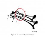
3. Remove the connectors from the horn solenoid leaving the jumper at the horn button connected. One wire should have 24v on it, the other should show continuity to ground. No continuity to ground = bad wire or connection to horn button. No 24v = bad wire or connection from circuit breaker to horn.
4. If #3 is good, measure in ohms mode between the two terminals on the horn solenoid. Will be anywhere between about 10 ohms and maybe 200 ohms, depending upon exactly what type of solenoid is installed. Doesn't really matter, as long as there is something there. No ohms reading = bad solenoid.
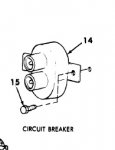
5. The only other possibility would be a circuit breaker that does not work under load. In this case, make a jumper at the solenoid from the hot wire you found in #3 to the solenoid terminal where the wire was. Ensure the other wire is hooked up to the solenoid. Remove the jumper at the horn button and reinstall the button. Measure volts from the jumper wire while pushing the horn button. If the voltage drops a bunch, it's probably a poor connection in the hot wire somewhere or a bad breaker.

Hope this helps....
Note that all this depends on good, clean grounds. Paint/rust/dirt is NOT a good ground. You are measuring, volts or ohms, between two points. If your leads do not make good contact, you won't get a valid reading, period.
 
Top