yertnamreg
Member
- 92
- 21
- 8
- Location
- Houston TX
I'm not a big fan of the incandescent bulbs used in our indicator display. I did a little digging and they are a standard 5mm size that you can also get LEDs in. The problem with LEDs is they aren't designed to handle the voltages these indicator lights use.
Most of the indicator bulbs in our dash are 24V. I still haven't found a good solution to replace these. However the turn signals and brights use 12V bulbs and there is a company out there making LEDs with integrated resistors for applications like this.
Parts:
Green LEDs
Blue LEDs
Spacers (I honestly would use ones that are slightly longer if I had to do this again)
Here's what I did:
1) Pull the indicator unit. Just pop out the four bolts on the front and the unit will lift out and let you unplug it.
2) Use a flat head screw driver to unscrew the four spring loaded screws on the back.
3) Pull the bulbs out for the two turn signals and the brights in the middle.
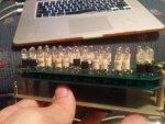
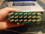
4) Insert the new LEDs. Polarity is important on these. The big trace at the top of the board is actually the ground. If you look at the board as it's installed in the dash the LED orientation is:
Left turn -> Flat side of LED to the right
Brights -> Flat side of LEDs to the left
Right Turn -> Flat side of LEDs to the left
5) Put it all back together and test it in the truck
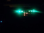
Its not a big modification, but it makes these indicators a lot more visible. FYI I chose to use blue for the brights even though the mask in the housing is green. The blue light still shines through nicely though.
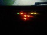
Before:
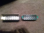
Housing when you take it apart:
LED Install:
After:
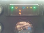
I'm still tweaking some things and will update when the install is more final, but wanted to share
Most of the indicator bulbs in our dash are 24V. I still haven't found a good solution to replace these. However the turn signals and brights use 12V bulbs and there is a company out there making LEDs with integrated resistors for applications like this.
Parts:
Green LEDs
Blue LEDs
Spacers (I honestly would use ones that are slightly longer if I had to do this again)
Here's what I did:
1) Pull the indicator unit. Just pop out the four bolts on the front and the unit will lift out and let you unplug it.
2) Use a flat head screw driver to unscrew the four spring loaded screws on the back.
3) Pull the bulbs out for the two turn signals and the brights in the middle.
4) Insert the new LEDs. Polarity is important on these. The big trace at the top of the board is actually the ground. If you look at the board as it's installed in the dash the LED orientation is:
Left turn -> Flat side of LED to the right
Brights -> Flat side of LEDs to the left
Right Turn -> Flat side of LEDs to the left
5) Put it all back together and test it in the truck
Its not a big modification, but it makes these indicators a lot more visible. FYI I chose to use blue for the brights even though the mask in the housing is green. The blue light still shines through nicely though.
Before:

Housing when you take it apart:

LED Install:


After:


I'm still tweaking some things and will update when the install is more final, but wanted to share
Last edited:


