• Steel Soldiers now has a few new forums, read more about it at: New Munitions Forums!

  • Microsoft MSN, Live, Hotmail, Outlook email users may not be receiving emails. We are working to resolve this issue. Please add support@steelsoldiers.com to your trusted contacts.


Undervoltage light on MEP-804A

First time poster and long time reader. Have several other model MEPs and pieces of military equipment, and not afraid to get my hands dirty.

I recently acquired an MEP-804A, after changing batteries and a new alternator, it is still showing an under voltage warning light at all times when running.

Batteries were bad and was not charging before, is charging now.

The under voltage light is on at all times when running. When in the start position, it creates a little over 200 volts per gauge and drops to zero when you let off S1. Fuse is good and tested for ohms.

I ran through TM 9-6155-645-24 section 2-55 and when i run it with the wire from terminal 5 on the voltage regulator disconnected, it does not shut off and the gauges were identical from before disconnecting it. Also tried disconnecting the warning light harness with no change as far as i can tell.

Should I continue to look at replacing the Over/Under voltage relay, or look towards testing the voltage regulator or MPU testing/adjusting?

Been reading through here and the TMs just trying to get a more experienced opinion before replacing the over/under voltage relay or voltage regulator
 

kloppk

Well-known member
Steel Soldiers Supporter
1,967
3,069
113
Location
Pepperell, Massachusetts
I'd suggest performing the AC Voltage Regulator Test per the -24 TM.
Be sure to use the correct test procedure. The 804's were built with two different AC Voltage Regulator systems.
Libby & TRC. Different test procedures depending on which VR is in the set.

You'll also want to verify someone didn't mix-n-match parts between the two AC Voltage Regulator Systems.
- AC Voltage Regulator, Transformer T1, Resistor R16 and the front panel AC Voltage adjust potentiometers are all different between the two systems.
Was having issues getting instructions for testing the voltage regulator, found some on:

4.1.2 - Testing. (Regulator. PIN: 19870 For MEP-804A Generator Set).
a. Shut down generator set.
b. Open output box access door.
c. Note position of voltage reconnection terminal board and set FREQUENCY SELECT switch to 60 Hz position.
d. Start generator set and turn VOLTAGE adjust potentiometer to ensure the adjustment ranges on TABLE 4-1 are
met, depending on position of voltage reconnection terminal board.
e. Shut down generator set.
f. If no voltage or Iow voltage was indicated, or voltage adjustment range could not be achieved, perform the following
steps. Otherwise, AC voltage regulator (2, FIGURE 4-1) is serviceable.
g. Disconnect wire 141 A from terminal 1 of AC voltage regulator.
h. Set multimeterfor DC volts and connect positive Iead to wire 141A. Connect negative lead of multimeter to terminal
3 of AC voltage regulator. Start generator set and operate at rated frequency. Move and hold MASTER SWITCH
in START position. Multi meter should indicate between 4 and 12 VDC.
i. Shut down generator set. Isolate wire 141A.
j. Set multimeter for AC volts and connect to terminals 10 and 11 of AC voltage regulator. Start generator set and
operate at rated frequency. Move and hold MASTER SWITCH in START position. Multimeter should indicate 110
to 160 VAC.
k. Shut down generator set.
l. Disconnect wire 137A from terminal 5 of AC voltage regulator. Set multimeter for ohms and connect positive lead
to wire 137A and negative lead to terminal 4 of AC voltage regulator. Move VOLTAGE adjust potentiometer to full
counterclockwise position. Multimeter should indicate no more than 2 ohms with FREQUENCY SELECT switch
in 60 Hz position or 50 Hz position. Move VOLTAGE adjust potentiometer clockwise slowly while observing multimeter. Multimeter should increase smoothly to approximately 20,000 ohms.
m. If steps h, j, and I are as indicated above, AC voltage regulator is defective and must be replaced.
n. Connect all wires previously disconnected.
o. Close output box access door


H is 10.8 vdc
J is 153 vac across wires 10 and 11 (disconnected from regulator and in start) and 15.5 just running
L is .7 to 19.8 in 20k ohm and 60hz and .1 to 18.9 in 20k ohm and 50hz


So in this assumption voltage regulator? it was also only half attached to the generator and wires were all numbered, so may of been removed for testing and being sold at DRMO
 

kloppk

Well-known member
Steel Soldiers Supporter
1,967
3,069
113
Location
Pepperell, Massachusetts
That's NOT the test procedure for the LIBBY AC Voltage Regulator. That's one is for the TRC AC Voltage Regulator.

The one for the LIBBY is -24 TM dated 1 May 2008 paragraph 4-1.1

4-1.1 Testing (AC Voltage Regulator, P/N 01-21501-1, for MEP-804A/MEP-804B).
a. Shut down generator set.
b. Open output box access door.
c. Note position of voltage reconnection terminal board and set FREQUENCY SELECT switch to 60
Hz position.
d. Start generator set and turn VOLTAGE adjust potentiometer to ensure adjustment ranges on
Table 4-1 are met, depending on position of voltage reconnection terminal board.
e. Shut down generator set.
f. If no voltage or low voltage was indicated or voltage adjustment range could not be achieved,
perform the following steps. Otherwise, AC voltage regulator (2, Figure 4-1) is serviceable.
g. Disconnect wire 141A from terminal 1 of AC voltage regulator.
h. Set multimeter for DC volts and connect positive lead to wire 141A. Connect negative lead of
multimeter to terminal 3 of AC voltage regulator. Start generator set and operate at rated
frequency. Move and hold MASTER SWITCH in START position. Multimeter should indicate
between 4 and 12 VDC.
i. Shut down generator set. Isolate wire 141A.
j. Set multimeter for AC volts and connect to terminals 10 and 11 of AC voltage regulator. Start
generator set and operate at rated frequency. Move and hold MASTER SWITCH in START
position. Multimeter should indicate 210 to 280 VAC.
k. Shut down generator set.
l. Disconnect wire 137A from terminal 5 of AC voltage regulator. Set multimeter for ohms and
connect positive lead to wire 137A and negative lead to terminal 4 of AC voltage regulator. Move
VOLTAGE adjust potentiometer to full counterclockwise (CCW) position. Multimeter should
indicate approximately 3,000 ohms with FREQUENCY SELECT switch in 60 Hz position, and
approximately 0 ohms with FREQUENCY SELECT switch in 50 Hz position. Move VOLTAGE
adjust potentiometer slowly clockwise (CW) while observing multimeter. Multimeter should
increase smoothly to approximately 10,000 ohms.
m. If steps h, j, and l are as indicated above, AC voltage regulator is defective and must be replaced.
n. Connect all wires previously disconnected. Close output box access door.
 

Guyfang

Moderator
Staff member
Moderator
15,881
22,131
113
Location
Burgkunstadt, Germany
KEEP IN MIND!!!!!!!!! You need to look at all the components to be sure that all the parts in it, are for the VR that are in the set. And since it was unhooked, I would be checking all the wires, to be sure they are hooked up right.

If I had a 804A, I would order a replacement VR from Kurt, and toss the one in the set, out into the trash. Even if it works, it will co bad sooner or later. But that's just my 2 cents worth.
 
@kloppk

for h it is 10.54vdc
for J touching probes to 10 and 11 when still connected and in start is 154
for L it is showing .05 to 18.9 on 60hz and .03 to 18.9 with the setting at 20k ohms

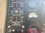
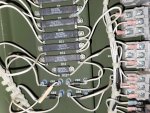
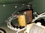
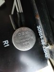
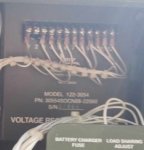
based on those numbers it looks like it should be the TRC regulator? there was a paper tag taped next to the regulator as well. pics below of what i can see in the dark of the transformer and everything.

396050687_294816003472527_4970631080744827623_n.jpg367392833_1087643535558843_4524245519375800343_n.jpg370315394_1406523379959571_6234563428906846555_n.jpg370762326_341571881743268_1750757321689420734_n.jpg
 

kloppk

Well-known member
Steel Soldiers Supporter
1,967
3,069
113
Location
Pepperell, Massachusetts
Looks like someone put a LIBBY AC Voltage Regulator in by mistake!

The Transformer T1 in your picture is a TRC Transformer for a TRC AC Voltage Regulator setup.
The front panel potentiometer R1 is a 20K ohm one which is for a TRC AC Voltage Regulator setup.
You don't have a picture of R16. R16 is mounted on the back of the 50/60 Hz Switch.
(The resistors you have a picture of does not include R16.)

The earlier picture you posted is of a LIBBY AC Voltage Regulator!
Libby VR.jpg


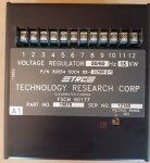
Here is a Technology Research Corporation (TRC) AC Voltage Regulator.
TRC VR.jpg


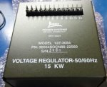
This is a LIBBY AC Voltage Regulator
Libby VR1.jpg

No wonder your set isn't making power!
 
Top
AdBlock Detected

We get it, advertisements are annoying!

Sure, ad-blocking software does a great job at blocking ads, but it also blocks useful features of our website like our supporting vendors. Their ads help keep Steel Soldiers going. Please consider disabling your ad blockers for the site. Thanks!

I've Disabled AdBlock
No Thanks