Good stuff, ac! Thanks very much. I'm sure this will be useful for lots of folks.
I'm going to be stubborn and run a separate lead for the GP system. Sounds like a 150 amp CB will do just fine. 120 should do, but I can't find any listings for that size.
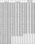
Looking at various online ampacity tables, I'm getting different answers for cable size. Off the top of my head with no calculations, I was thinking something like 4 AWG would be plenty, but some tables are telling me I need to go up to 1 ga. That can't be right.
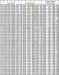
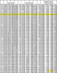
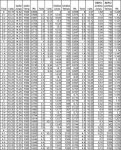
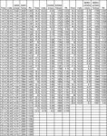
This one suggests I'll be fine with 4 AWG. But that's max current. Doesn't say anything about voltage drop.
Assuming a 6 foot length,
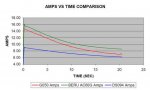
this one tells me that 120 amps will give me a 2.4% voltage drop @ 90C in a 12v system using 2 AWG. That's certainly more than acceptable.
Actually, given the relatively short load duration, I think 4 ga. is plenty big, even overkill. Might drop down to 6.
What do you think?


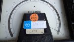
 18.3 KB Views: 51
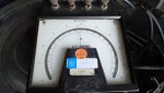
 13.3 KB Views: 53