

mistaken1
New member
- 1,467
- 6
- 0
- Location
- Kansas City, KS
It looks to me like you are putting two coils in series. The coil (solenoid) on the starter (24V) and the ford coil (12V or 24V ????). When you put two coils in series they share the available voltage, which means neither one gets the proper voltage to operate.
The starter solenoid is designed to work at 24V. If you have 24V on the purple wire at the starter solenoid that solenoids path to ground passes through the ford relay where it is designed to work at ?? volts.
Assuming your ford relay is 24V your coils need to be in parallel.
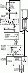
According to the attached diagram when you send voltage to “S” on the starter solenoid the path goes through a solenoid coil to “M” on the attached diagram and then through the contacts back to “B” on the solenoid and to “S” on the relay through that relay coil and then from “I” on the relay to ground (negative).
I still do not understand how this is supposed to solve any heat issues as the starter and its solenoid are still together and still subject to heat.
As doghead pointed out the stock CUCV system already implements this relay control of the power going to the starters as part of the 24V starting system. If you are concerned about heat in the wires that feed the starter and its solenoid then just replace them with larger wires in the stock control configuration. The whole point to the doghead modification is to replace the stock starter relay with a heavy duty unit which is what you are trying to do with the ford relay. Why try to reinvent the wheel?
As far as heat goes unless you are running headers that sit close to the starter generating more heat in a closer proximity to the starter than the original design why waste time and money changing something when these trucks have been starting in their stock form for 25+ years?
Not picking on you, I just don't understand why you want to do what you want to do, none the less I will do what I can to help you accomplish your goals.
The starter solenoid is designed to work at 24V. If you have 24V on the purple wire at the starter solenoid that solenoids path to ground passes through the ford relay where it is designed to work at ?? volts.
Assuming your ford relay is 24V your coils need to be in parallel.
According to the attached diagram when you send voltage to “S” on the starter solenoid the path goes through a solenoid coil to “M” on the attached diagram and then through the contacts back to “B” on the solenoid and to “S” on the relay through that relay coil and then from “I” on the relay to ground (negative).
I still do not understand how this is supposed to solve any heat issues as the starter and its solenoid are still together and still subject to heat.
As doghead pointed out the stock CUCV system already implements this relay control of the power going to the starters as part of the 24V starting system. If you are concerned about heat in the wires that feed the starter and its solenoid then just replace them with larger wires in the stock control configuration. The whole point to the doghead modification is to replace the stock starter relay with a heavy duty unit which is what you are trying to do with the ford relay. Why try to reinvent the wheel?
As far as heat goes unless you are running headers that sit close to the starter generating more heat in a closer proximity to the starter than the original design why waste time and money changing something when these trucks have been starting in their stock form for 25+ years?
Not picking on you, I just don't understand why you want to do what you want to do, none the less I will do what I can to help you accomplish your goals.
Attachments
-
 26.7 KB Views: 16
Last edited: