• Steel Soldiers now has a few new forums, read more about it at: New Munitions Forums!

  • Microsoft MSN, Live, Hotmail, Outlook email users may not be receiving emails. We are working to resolve this issue. Please add support@steelsoldiers.com to your trusted contacts.


winch assembly problem

m16ty

Moderator
Moderator
Steel Soldiers Supporter
9,576
210
63
Location
Dickson,TN
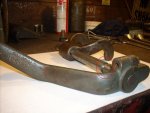
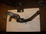
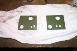
I'm trying to get my winch back together after replacing all the seals. I took the winch apart about a year ago so it's kind of fuzzy on where all the parts go back.

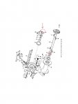
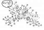
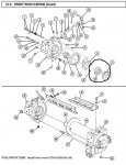
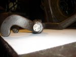
The problem is a thrust washer (part number 2286131, item 31 on page 35 of TM9-3830-206-34P). TM9-3830-206-34P shows the washer to go between the worm gear housing and the drum. When I put the washer in this position it seems the drum isn't going against the worm housing far enough (it's hitting the thrust washer). Could the TM be wrong on the location of the washer because there doesn't seem like there's enough space for it where it is.
 

m16ty

Moderator
Moderator
Steel Soldiers Supporter
9,576
210
63
Location
Dickson,TN
I figured it out. After taking the drum on and off a few times and seeing how things fit up I found out that that's not where the washer goes. Unless I'm missing something it looks like the TM is wrong.

Looks as if the thrust washer in question goes between the drum and the shift collar on the shifter side of the winch. I've got it all together and everything fit up nicely after I got the washer in the right place.
 

m16ty

Moderator
Moderator
Steel Soldiers Supporter
9,576
210
63
Location
Dickson,TN
Sorry, I didn't take any pics. Here's the parts breakdown out of the TM (which is wrong). Item #31 (circled) accually goes where the other circle and arrow is.
 

Attachments

m16ty

Moderator
Moderator
Steel Soldiers Supporter
9,576
210
63
Location
Dickson,TN
Well I've run into another problem. Got the winch together and the shifter positions doesn't line up with the detents. To completely disengage the winch you have to move the shifter way past the detent and when you engage the lever it won't go all the way to the other detent.

I've assembled and removed the shifter side of the winch several times, swapped out the shifting fork with one out of a parts winch, and took lots of measurements. I can't figure out what's going on. Thought maybe the shift rod could be twisted but it doesn't appear to be.

I'm bad about over thinking things sometimes. Am I overlooking something simple? At this point the only thing I can think of to fix it is to make another detent plate with new holes that line up in the correct position.
 

gringeltaube

Staff Member
Super Moderator
Moderator
Steel Soldiers Supporter
6,882
2,260
113
Location
Montevideo/Uruguay
It might very well be twisted!
Two of my parts winches have that rod twisted off, broken inside the housing.
Will pull a new one tomorrow to see how it looks like....

G.
 

m16ty

Moderator
Moderator
Steel Soldiers Supporter
9,576
210
63
Location
Dickson,TN
I've seen them broke also. They seem to break where the groove is cut into them. That leads me to believe they would break before they would twist but I could be wrong.

If you have a shaft handy, I'd like to know what the relationship is between the two keyways (the one in the shifter and the one in the fork). That should tell me if my shaft is twisted.
 

DieselBob

Active member
2,891
13
38
Location
Arnold Maryland
In [FONT=Arial, sans-serif]TM 9-2320-361-34 it shows the thrust washer on the other end of the drum. Opposite the worm gear housing and one at the shift fork

From the TM
Install drum (17), thrust ring (16), and two new woodruff keys (15) on drum shaft (22).

[/FONT][FONT=Times New Roman, serif]Install thrust ring (24), drum sliding clutch (23), and new seal (26) in end frame (31).[/FONT]

[FONT=Arial, sans-serif]The TM would indicate there is a "thrust ring" on each side of the the "drum sliding clutch".
[/FONT]
 

Attachments

Last edited:

m16ty

Moderator
Moderator
Steel Soldiers Supporter
9,576
210
63
Location
Dickson,TN
In [FONT=Arial, sans-serif]TM 9-2320-361-34 it shows the thrust washer on the other end of the drum. Opposite the worm gear housing and one at the shift fork [/FONT]

[FONT=Arial, sans-serif]From the TM[/FONT]
[FONT=Arial, sans-serif]Install drum (17), thrust ring (16), and two new woodruff keys (15) on drum shaft (22).[/FONT]

[FONT=Times New Roman, serif]Install thrust ring (24), drum sliding clutch (23), and new seal (26) in end frame (31).[/FONT]
I saw that tonight when I was looking into my shifter problem. That TM is right. The TM9-3830-206-34P is wrong.

I wonder what the military would think if I filled out that little form in the back (where you submit corrections) and mailed it to them?
 
Last edited:

DieselBob

Active member
2,891
13
38
Location
Arnold Maryland
[FONT=Times New Roman, serif][FONT=Arial, sans-serif]That's what happens when the guberment gets involved. Most likely to different agencies did the 2 TM's and never encountered the other.
[/FONT]
[/FONT]
 

gringeltaube

Staff Member
Super Moderator
Moderator
Steel Soldiers Supporter
6,882
2,260
113
Location
Montevideo/Uruguay
...............................
Will pull a new one tomorrow to see how it looks like....

G.
...well, it wasn't a new one but working properly at least...

Shown below is the complete shift assembly with the lever and fork firmly in place, laid on level ground. I was trying to give a kind of reference for the relative position of both parts mounted to the shaft... Strangely the two keyways on this one are not diametrally opposed but at approx. at 173º -174º to each other. Not sure if that is normal, maybe someone can confirm this on a brand new shaft?

I would say that if a shaft was twisted as much as to fall out of range of the detents it probably is also bent and about to break off right at that groove for the positioning screw.
At least I could see now why they twist/ break so easily! (2nd pic, red circle) Very questionable engineering BTW, to end up with such a weak spot in between lever and fork, just where the maximum stress is to be expected...!? There is a much simpler way to secure that assembly in place and it would be with a solid 3/4" shaft! (more on this, coming soon....!)

G.
 

Attachments

m16ty

Moderator
Moderator
Steel Soldiers Supporter
9,576
210
63
Location
Dickson,TN
Well, I had another parts winch so I pulled the shaft out of it but it was rusty around the sealing surface (and everywhere else) so I figured I better not use it. The original shaft doesn't have any signs of twisting but the something is definately out of adjustment.

Since I didn't have a spare shaft to use I did the only thing I could with what I had. I welded up the original holes and moved the holes. It works fine now. The pic on the left is a factory detent plate and the one on the right is the plate with the holes moved. You can see by the pic how much it was off.
 

Attachments

gringeltaube

Staff Member
Super Moderator
Moderator
Steel Soldiers Supporter
6,882
2,260
113
Location
Montevideo/Uruguay
Wow, that's way off... and that sure is a practical solution...![thumbzup]

One day more sooner than later you will find out what was wrong, meanwhile you have a good working winch!

G.
 

m16ty

Moderator
Moderator
Steel Soldiers Supporter
9,576
210
63
Location
Dickson,TN
The more I look at the pic I took, The holes aren't off as much as it looks in the pic. It appears the pic is centered on the stock plate and the "modified" plate is shot at a angle (I'm not the best at taking pics). The holes were accually moved to where one hole is almost between the two original holes and the other hole is to the left of it (the same distance apart as original).
 
Last edited:

treeguy

New member
605
3
0
Location
Fort One Bay - Cape Cod, MA
I am pulling my hair out with the same clutch handle problem. I have taken off the clutch side of the winch to see what is the hold up. The nipples on the inside of the forks look like they have too much gap to the bottom of the channel in the clutch engagement unit and the ears of the forks cannot fully engage the clutch because they hit the outer edge of the cavity in the drum for the clutch. This is my reason for the shifter not engaging into the detent holes. And NO the shifter shaft is not twisted. So here is my theory - someone replaced the shifter fork with a 10 Ton winch fork. You guys with 10 Ton winches, are these guts the same as in yours? Does the shifter fork have the same diameter rod to actuate the handle. I am going to call Memphis to see if they have a fork but I would appreciate any input before I loose my grip. Thanks
 

treeguy

New member
605
3
0
Location
Fort One Bay - Cape Cod, MA
I just received the winch parts that I had ordered from Memphis. The new clutch shifter shaft has the keys 180 degrees opposite from each other (for the fork and the handle). I dry fit the new shaft and this is the SOLUTION! Having the key ways 180 from eachother allows the handle detent ball to line up perfectly with the holes in the winch plate. This seems to be strange, was there some Monday/Friday machining going on on the original parts or have the shafts indeed been twisted by forcing the clutch handle? I would swear that my original clutch shaft was not twisted, there are no stress marks that would lead me to think it was. It looks perfect even in the location of where it is shaved/reduced for the set screw near the handle. If anyone else has the handle not lining up with the ball holes, try a new shaft from Memphis for $23.06. Also I ordered a new fork unit which has tighter ears to themselves which fit into the channel of the clutch seemingly better. This is just what I'm going thru, others might have other problems.
:grd:
 
Top
AdBlock Detected

We get it, advertisements are annoying!

Sure, ad-blocking software does a great job at blocking ads, but it also blocks useful features of our website like our supporting vendors. Their ads help keep Steel Soldiers going. Please consider disabling your ad blockers for the site. Thanks!

I've Disabled AdBlock
No Thanks