• Steel Soldiers now has a few new forums, read more about it at: New Munitions Forums!

  • Microsoft MSN, Live, Hotmail, Outlook email users may not be receiving emails. We are working to resolve this issue. Please add support@steelsoldiers.com to your trusted contacts.


Working on the M37

mkcoen

Well-known member
Steel Soldiers Supporter
5,637
380
83
Location
Spring Branch, TX
After 3 years of owning it we've finally started working on the wife's M37. Somehow in 3 years time I haven't managed to take any photos of it (that I can find) so no real "before" pictures to give you any idea of how bad it was (is).

The truck came from PA via eBay. The lying POS that sold it to me assured me there was very little rust. From the beginning of that sentence you should be able to tell how much there actually was. Unfortunately I didn't find Steel Soldiers until after I took delivery or I might have gotten a much better vehicle to begin with.

I already have a thread about the lovely condition of the brakes:
http://www.steelsoldiers.com/m37/71788-m37-brake-wheel-cylinders.html

I purchased a parts truck a while back and have the bed from that vehicle in pieces for a little later.

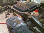
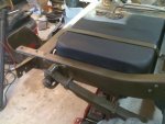
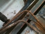
For now we've started working on the frame since the old rusted one (bed) has been removed.

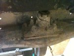
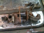
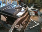
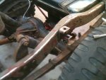
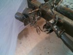
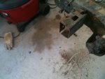
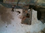
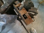
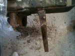
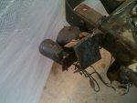
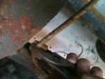
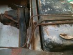
First thing starting at the rear was to repair the tail light guards. These were pretty twisted but straightened out well with just a little help from a bench vise and crescent wrench. The right bracket we had to remove and straighten but the left we were able to pull back in line bolted to the frame.

Pics:
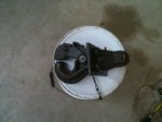
1) Right tail light guard
2) Right tail light guard removed
3) Right tail light guard after repair
4) After repair #2
5) Left tail light guard before
6) Left tail light bracket after repair
 

Attachments

Last edited:

mkcoen

Well-known member
Steel Soldiers Supporter
5,637
380
83
Location
Spring Branch, TX
While the bed is off I wanted to clean up the lines going to the fuel tank. After nearly 60 years these are pretty gunked up with mud and rust. The lines seem to be solid so I don't want to go to the expense and hassle of replacing them if I don't have to but I'd like to get the crud out so they don't rust out down the line quicker.

What I did was simply take a pair of pliers and lightly grip the spring then twist it back and forth around the line. This was enough to break loose any mud and rust that was making contact between the spring and lines. You want to be careful and support the line with your other hand while you're doing it so as not to put too much pressure on the line itself. I took a wire bruch to it before and after just to help loosen and clean stuff off.

The springs were bad enough in places that they were rusted through (or close enough that cleaning broke them) but again, this isn't a show truck just a driver so I'm not real concerned about what it looks like from underneath.

Pics:

1) Before
2) Pliers gripping the spring
3) After
 

Attachments

vtdeucedriver

Well-known member
2,523
38
48
Location
Vermont
Your brake lines will be in the same condition. Please do yourself a favor and replace those or make your own. The m37 needs all the help it can get for stopping.
 

TexAndy

Active member
1,427
15
38
Location
Bee County, Texas
I wonder if we could put a fitting or something on it to apply regulated pressure to the system with your air compressor. that way we could visually inspect the lines to see if there's any slow leaks while it's all exposed like this.
 

DAP

New member
169
1
0
Location
Waxhaw, NC
Wow you have a lot of rust. Reminds me of the way I started on my current M37 "20 year rebuild project". I want to watch this rebuild and see how you are doing.
 

linx310

New member
478
0
0
Location
texas
Yea I would replace the lines. I tried to save the lines on my 52 m38a1 and it caused more problems then it was worth. All it takes is a pin hole in one of the lines and it screws up the entire breaking system.
 

scrapdaddy

Member
Steel Soldiers Supporter
409
11
18
Location
Dittmer, Mo.
While I had the tank off on mine, I replaced all the lines with new. Just buy the straight lines from Napa and bend yourself. Not too bad of a job. Brakes and fuel lines should not be overlooked [ wife's truck ] Good luck.
 

mkcoen

Well-known member
Steel Soldiers Supporter
5,637
380
83
Location
Spring Branch, TX
Thanks for all of the encouragement guys.

The reason I started this thread was for guys working on these for the first time not the ones that have done a dozen of them. Hopefully the photos I add and the issues that I come up with will be of help.

Having said that, here is what the pintle looks like. There are 11 pieces starting from inside the frame rail:
1) Castle nut
2) Washer
3) Rear plate (I should have stood this on it's side in the picture for a better idea of what it looks like)
4) Intermediate plate
5) Front Plate (again not a good shot in photo as it looks connected to the pintle
6) Main pintle body and shaft
7) Upper part of pintle with 2 pivot pins with grease fittings
8) Spring (for some reason when I put 8 in here I get a emoticon)
9) Release handle (the 2 pivot pins make it add up to 11)

I have no idea what these are actually called because I don't have a copy of the TM handy it's just what I call them.

The pivot pins are held on by a small circular spring on each one. They're kind of hard to see in the picture and harder to see under a coat of paint, grease, and dirt. It's fairly easy to pry up the edge with a pocket knife then use some needle nose pliers to get them off.

Pics:
1) Before!
2) Parts laid out in order of assembly
3) Pivot pin with spring
4) Spring by itself.
 

Attachments

Last edited:

usmctopgun

Member
209
0
18
Location
Cochran, GA
Saw one of these today at a buddy of mines place, it was a 41' USMC model he is restoring the cab and bed, but turning it into a more capable offroad model. Cool trucks.
 

mkcoen

Well-known member
Steel Soldiers Supporter
5,637
380
83
Location
Spring Branch, TX
Here's a shot of the pintle after paint. I want to get some new bolts for it before I put it back on but it's lubed up and ready to go.

We've been trying to get some major body work done on the driver's side cab corner. It had been damaged at one point and their idea of repairs was to wail on it with a ballpeen hammer. It's just about back in the correct position and once that's done we can get rolling on the regular body work.
 

Attachments

mkcoen

Well-known member
Steel Soldiers Supporter
5,637
380
83
Location
Spring Branch, TX
Here's a couple of pics working on the rear frame and fuel tank. As this is a "motorpool" restoration I don't want to undue anything that would keep the vehicle from driving. In other words I don't want to take a chance of disconnecting the fuel tank to find out something screwy happened in the process and the truck won't start afterwards.

I took one tank strap off and did that side of the tank, put it back on, then did the other side of the tank. The bottom straps stayed attached and I supported the tank with a jack and large plastic tool box to spread out the weight. The bottom side of the tank and straps will be painted in place after considerable cleaning. I'm just doing this part now so we can start reassembly of the bed.

Also I'm doing all of this with rattle cans of Gillespie from Rapco. The main body will be done with a spray gun but since I'm only doing small pieces at a time now I don't want to have to mix paint and clean the gun 20 times to get this part done.

Pics:
1) Left frame rail and tank before painting
2) Left frame 2
3) Right frame rail and tank after painting
4) Right frame 2
 

Attachments

Keith_J

Well-known member
3,657
1,313
113
Location
Schertz TX
Yea I would replace the lines. I tried to save the lines on my 52 m38a1 and it caused more problems then it was worth. All it takes is a pin hole in one of the lines and it screws up the entire breaking system.
I'm up for that, he has the deluxe double flare kit with toggle tube clamp. Rusted fittings will need torch heating to remove, this worked on the rear hose. Bending long sections is relatively easy, the master cylinder to frame bulkhead was a bit of a chore, being only 8" long and having a ? shape.

The bed patch panel just got easier. Harbor Freight has inexpensive butt welding clamps which should work like a champ to align the edges for TIG welding. Backing these up with aluminum heat sinks will assure minimal distortion with pulsed TIG. I have a recommendation of 40 pulses per second, 40% background current and 50 amperes base should work like a charm. The cross member welding induced a bit of distortion which took a bit of force to correct.
 
Top
AdBlock Detected

We get it, advertisements are annoying!

Sure, ad-blocking software does a great job at blocking ads, but it also blocks useful features of our website like our supporting vendors. Their ads help keep Steel Soldiers going. Please consider disabling your ad blockers for the site. Thanks!

I've Disabled AdBlock
No Thanks