Demoh
Member
- 217
- 26
- 18
- Location
- St Pete, FL
Ive been working on 1 particular unit for a little bit now after taking care of the engine side of things on an 803a. I can hear everybody now, yes I am running through the -24 and related docs. I normally wouldnt post if it wasnt some weird compound issue, or maybe my brain lacking direction / where to start on these complex issues.
Im hoping all of these problems are related in some way but staring at the schematics (btw, what happened to the high-res colored in the sticky? I had to find the CMEC layered one so the words are readable) until my head hurts I had to take a break.
Here is a list of the problems:
- No "pull" on L5 fuel solenoid. - ignore this, probably bad L5 or bad wire, deadcrank works so K2 is fine.
- Oil pressure gauge jumps from 60 to 80 when you turn panel lights on - sometimes erratic movement
- no coolant temp reading 90% of the time. When panel lights are on the coolant temp needle goes high erratically. Sometimes without panel lights coolant temp needle moves to high side (right)
- oil pressure switch theory of operation question - is the OP switch supposed to be NC when 0 psi and open when operating or vice versa? Either way in my troubleshooting I had to disconnect K20 and jump it in order to get power through K20 to K1 to close it, but I am thinking now that caused my issue with the OP switch because I tried to test it by disconnecting the OP switch to shut the unit down, it didnt shut down so I shorted the leads and it still didnt shut down. (In hindsight I think I just answered my question however I would still like to know the theory of operation from people smarter than me)
- both float switches are bad due to corrosion so its completely disconnected until I can get a replacement. (also theory of operation, magnets down = open, magnets up = closed, or does the float module invert the signals so down = closed and up = open, but after A9 its inverted?)
unit stopped cranking when moving S1 to start the starter engages for 1/6 of a rotation then quits. I may have caused this by swapping K20 with whatever is adjacent to it. Currently using deadcrank to start the unit. (im not sure on timing for when this problem started)
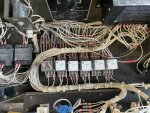
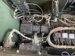
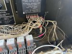
For the relays since I suspected a bad relay I ohmed the contacts. Knowing my meter is out of cal and shorting the leads shows about 5ohms, I found 1 NC contact on K20 which was reading about 10ohms. Because I couldnt confirm instrument error I swapped K20 with K19. I was still having issues after this which lead me to believe the relay was fine, so I proceeded to disconnect A and B from K20 and jump it with 24v manually so I could close K1. The whole reason I did this is because I needed to force the set to make power. (surprisingly, it does, S6 still needs to be cleaned though)
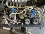
Unit has evidence of having the harness repaired. Its a pretty old Libby unit that looks like its been refreshed multiple times based on how many layers of CARC are on it and how rough everything is.
My next steps: use a different meter and replace the relays with known good / new relays. Test/Replace L5, (hoping for brilliant forum ideas at this point), then check wire for correct terminations and continuity.
Im thinking there is some wire issue with either gauges not getting enough juice causing erratic readings or a grounding issue.
Im hoping all of these problems are related in some way but staring at the schematics (btw, what happened to the high-res colored in the sticky? I had to find the CMEC layered one so the words are readable) until my head hurts I had to take a break.
Here is a list of the problems:
- No "pull" on L5 fuel solenoid. - ignore this, probably bad L5 or bad wire, deadcrank works so K2 is fine.
- Oil pressure gauge jumps from 60 to 80 when you turn panel lights on - sometimes erratic movement
- no coolant temp reading 90% of the time. When panel lights are on the coolant temp needle goes high erratically. Sometimes without panel lights coolant temp needle moves to high side (right)
- oil pressure switch theory of operation question - is the OP switch supposed to be NC when 0 psi and open when operating or vice versa? Either way in my troubleshooting I had to disconnect K20 and jump it in order to get power through K20 to K1 to close it, but I am thinking now that caused my issue with the OP switch because I tried to test it by disconnecting the OP switch to shut the unit down, it didnt shut down so I shorted the leads and it still didnt shut down. (In hindsight I think I just answered my question however I would still like to know the theory of operation from people smarter than me)
- both float switches are bad due to corrosion so its completely disconnected until I can get a replacement. (also theory of operation, magnets down = open, magnets up = closed, or does the float module invert the signals so down = closed and up = open, but after A9 its inverted?)
unit stopped cranking when moving S1 to start the starter engages for 1/6 of a rotation then quits. I may have caused this by swapping K20 with whatever is adjacent to it. Currently using deadcrank to start the unit. (im not sure on timing for when this problem started)
For the relays since I suspected a bad relay I ohmed the contacts. Knowing my meter is out of cal and shorting the leads shows about 5ohms, I found 1 NC contact on K20 which was reading about 10ohms. Because I couldnt confirm instrument error I swapped K20 with K19. I was still having issues after this which lead me to believe the relay was fine, so I proceeded to disconnect A and B from K20 and jump it with 24v manually so I could close K1. The whole reason I did this is because I needed to force the set to make power. (surprisingly, it does, S6 still needs to be cleaned though)
Unit has evidence of having the harness repaired. Its a pretty old Libby unit that looks like its been refreshed multiple times based on how many layers of CARC are on it and how rough everything is.
My next steps: use a different meter and replace the relays with known good / new relays. Test/Replace L5, (hoping for brilliant forum ideas at this point), then check wire for correct terminations and continuity.
Im thinking there is some wire issue with either gauges not getting enough juice causing erratic readings or a grounding issue.