• Steel Soldiers now has a few new forums, read more about it at: New Munitions Forums!

  • Microsoft MSN, Live, Hotmail, Outlook email users may not be receiving emails. We are working to resolve this issue. Please add support@steelsoldiers.com to your trusted contacts.


LMTV CTIS Question

Suprman

Well-known member
Supporting Vendor
6,840
654
113
Location
Stratford/Connecticut
On the m939a2 trucks there was an upgrade for running higher pressure. It was a newer ecu, replacement pressure sensor and wheel valve upgrades to what appears to be the same ones as the lmtv uses. Is there any way to trick the first gen lmtv systems into running higher pressure by just changing the pressure sender? Or putting a small resistor inline with one of the sensor wires so the system thinks the pressure is slightly lower than it really is.
Will
 

Stellaevil

Active member
120
48
28
Location
Michigan
On the m939a2 trucks there was an upgrade for running higher pressure. It was a newer ecu, replacement pressure sensor and wheel valve upgrades to what appears to be the same ones as the lmtv uses. Is there any way to trick the first gen lmtv systems into running higher pressure by just changing the pressure sender? Or putting a small resistor inline with one of the sensor wires so the system thinks the pressure is slightly lower than it really is.
Will
The sensor is a atmospheric or PSIA so normal atmosphere it puts out roughly .573 volts at .039psi/volt. Say 80psi = 3.12v. If you put in a "Resistor Divider" designed to reduce the signal wire voltage by 10% the system will see 80psi tires as 72psi and what it thinks is now 80psi tires would actually be 88psi (roughly). Keep in mind that atmospheric reading is now 10% low and if you live on a mountain the lower reading could cause a Fault. The more important issue is that the wheel valve on the LMTV front left can't close much above 84psi on a warm day. Resistor Divider = 3 resistors configured properly across the signal and ground wires.
 

Suprman

Well-known member
Supporting Vendor
6,840
654
113
Location
Stratford/Connecticut
Why is the front left different than the other valves? I was thinking I would only have to put a resistor on the positive side not the ground.
 

Stellaevil

Active member
120
48
28
Location
Michigan
Why is the front left different than the other valves? I was thinking I would only have to put a resistor on the positive side not the ground.
The front QRV is mounted on the right side frame rail so there is allot longer tubing to get to the left hub. That extra tubing make it harder for the valve to close at higher tire pressures and it get's worse as the valve diaphragms get's colder. Messing with the transducer supply current may cause problems that's why it should be on the signal wire which is very high resistance. I am not advocating trying this.
 

Suprman

Well-known member
Supporting Vendor
6,840
654
113
Location
Stratford/Connecticut
I hope you dont mind me asking all these questions. On the M939A2 90 psi upgrade (for the M936A2 wrecker primarily) it appears to use the same wheel valves as the lmtv. How do these function properly.
 

wandering neurons

Active member
248
112
43
Location
Fallon, NV
Update on my CTIS problem (two blinks from HWY, then all five flashing)
Got the M939A2 parts kit, used everything except one o-ring and the cover plate, everything fit. Total difference in the action of the sleeve valves, they pop back when depressed.
However, no change in the original problem. I checked the overboard vent tube and it's clear.
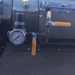
When I power up the truck (with shop air at 125psi), no noises, just the lights. When I de-power the truck, the pressure valve inside the cab pops (the one on the side of the PCU).

QQQ: Does anyone have a step-by-step guide of the operation of the CTIS computer and the PCU, electrically and pneumatically? I've got about six different versions of the Spicer troubleshooting guide, but I work very good at decomposing and troubleshooting a problem if I know in detail how it should be working when it is operational. (fixed an Allison RV transmission and a Dodge 3/4T diesel transmission that way)
Something along the lines of:
1. CTIS box powers on.
2. CTIS waits for pressure switch on wet tank to close
3. CTIS sends signal to PCU switch to check atmo press.
4. CTIS checks pressure on PCU
5. CTIS sends xxx psi to QRV
(something along those lines)
So I can figure out what should have happened when the CTIS flashes HWY and then five flashing, but no noises or pressure checks.
THX!
And good call on the M939A2 parts!
 

wandering neurons

Active member
248
112
43
Location
Fallon, NV
I've thought long and hard about it. My truck didn't have a CTIS computer in it when I got it, so I spent a few bucks on a used one. I suppose I could turn around and sell it and recoup my money....
Being lazy at the moment - You don't by chance have a good link to the manual system setup? If not, no sweat...

Have you considered just going manual as few others have done?
 

coachgeo

Well-known member
4,971
3,340
113
Location
North of Cincy OH
primary reason I plan to go this route is flexibility. Can go with higher pressures for highway use compared to military's fixed setting for that, as well as nearly infinite settings between max tire and minimum tire pressure settings. What can go wrong is NOT computer or electrical.. just the valves needing servicing. Removes on whole complexity of diagnosis and repair. KISS
 

wandering neurons

Active member
248
112
43
Location
Fallon, NV
KISS is good, especially as our LMTVs are already so complex. And I like being able to up the air pressure for highway beyond the CTIS limits.
I also asked the following question in the Manual CTIS thread, but this one is more active.
Did you have to pull a pair of lines across the cab right to left, to allow the valves to be on the driver's side?
Also, are are the valves and regulator using 1/4 NPT adapted to the air lines?
Thx!

primary reason I plan to go this route is flexibility. Can go with higher pressures for highway use compared to military's fixed setting for that, as well as nearly infinite settings between max tire and minimum tire pressure settings. What can go wrong is NOT computer or electrical.. just the valves needing servicing. Removes on whole complexity of diagnosis and repair. KISS
 

coachgeo

Well-known member
4,971
3,340
113
Location
North of Cincy OH
KISS is good, especially as our LMTVs are already so complex. And I like being able to up the air pressure for highway beyond the CTIS limits.
I also asked the following question in the Manual CTIS thread, but this one is more active.
Did you have to pull a pair of lines across the cab right to left, to allow the valves to be on the driver's side?
Also, are are the valves and regulator using 1/4 NPT adapted to the air lines?
Thx!
I've not bit that bullet yet so can't answer your questions. The fellow with the Australian outback FMTV build of recent did this on his and may be able to answer those questions
 
Last edited:

Smike740

Member
Steel Soldiers Supporter
199
13
18
Location
Columbus, Ohio
KISS is good, especially as our LMTVs are already so complex. And I like being able to up the air pressure for highway beyond the CTIS limits.
I also asked the following question in the Manual CTIS thread, but this one is more active.
Did you have to pull a pair of lines across the cab right to left, to allow the valves to be on the driver's side?
Also, are are the valves and regulator using 1/4 NPT adapted to the air lines?
Thx!
Yes you should be able to run the 2 lines behind the heater box and out above the accel pedal then run to the manual valve and regulator. You could also run the lines out through the left side front panel of the heater box similar to how the air lines run to the parking brake valve. I have the upgraded Heater + A/C box and may try this route. In either case I would tie the lines in at the right side of the cab where the existing lines go through the cab floor.
 

wandering neurons

Active member
248
112
43
Location
Fallon, NV
Thanks all for the info. I'm loath to pull the heater box to run lines, but will take a look and figure something out.
I'd still like the automatic system to work, I'm going to try a few more things as remote possibilities before throwing in the towel (and money).
I've got a few ideas on modifications to the basic idea, such as a two-position lever valve instead of the two ball valves - even simpler. The valve is either supplying pressure from the regulator to the QRV/wheels, or is vented to atmosphere. Maybe run the lines along the frame under the cab and thence into the cab on the drivers side.
But again, thanks much!

Yes you should be able to run the 2 lines behind the heater box and out above the accel pedal then run to the manual valve and regulator. You could also run the lines out through the left side front panel of the heater box similar to how the air lines run to the parking brake valve. I have the upgraded Heater + A/C box and may try this route. In either case I would tie the lines in at the right side of the cab where the existing lines go through the cab floor.
 

Pointman0853

Member
Steel Soldiers Supporter
319
13
18
Location
Gardnerville, NV
Manual CTIS

I've been running my CTIS in manual mode for over a year and would never go back to the computer setup. I did this primarily for reliability in the field, and flexibility in what pressures I can select.
Be careful with using too small a fitting as it will limit your fill times. I probably could have used smaller valves, but my setup works great and I am quite happy with the result.

Pointman
 

Attachments

Top
AdBlock Detected

We get it, advertisements are annoying!

Sure, ad-blocking software does a great job at blocking ads, but it also blocks useful features of our website like our supporting vendors. Their ads help keep Steel Soldiers going. Please consider disabling your ad blockers for the site. Thanks!

I've Disabled AdBlock
No Thanks