goodpoint turbo joeActually, depending on how the Mep802 behaves if the diesel engine stops it may open up the main contactor and disconnect itself.
-
Steel Soldiers now has a few new forums, read more about it at: New Munitions Forums!

802A Parallel operation ???
- Thread starter bohunk
- Start date

More options
Who Replied?ETN550
New member
- 457
- 9
- 0
- Location
- Knoxville, TN
All these threads ever talk about is getting the two sets synchronized. If there is not a master and slave governor and a master and slave voltage regulator then it is hightly likely a voltage regulator will be smoked. Load is a function of fuel position and with mechanical governors and some droop getting the two units to share fuel through careful adjustment might get one close to 25% 75% sharing or better. But each voltage regulator will be driving the field and whichever regulator is set ever so much greater than the other will continue to apply field until it meets the voltage. At no load this means that one or the other will be doing all the work. At full load it means the same thing and that could destroy the voltage regulator. With one unit the regulator is protected because the unit has high voltage sensing causing the interrupter to open. However with 2 units paralleled the lazy unit will keep lowering its field current and the working unit will try to pick it up and it will not be able to go over voltage and trip out. Instead it will fry the regulator.
A better solution if not retrofitting the controls would be to install a large capacity regulator in the master unit and run it normally. Then when the slave unit is needed only run it in parallel with the master and wire the fields together so both fields are fed by one regulator. The governors can be adjusted to get equal % on the load meters.. Then the slave unit could only be run as a slave and never by itself. BUT this still gives the advantage of one unit for smaller loads and two units for bigger loads.
A better solution if not retrofitting the controls would be to install a large capacity regulator in the master unit and run it normally. Then when the slave unit is needed only run it in parallel with the master and wire the fields together so both fields are fed by one regulator. The governors can be adjusted to get equal % on the load meters.. Then the slave unit could only be run as a slave and never by itself. BUT this still gives the advantage of one unit for smaller loads and two units for bigger loads.
Last edited:
Dieselfumes
New member
- 3
- 0
- 0
- Location
- Central Florida
I'm bumping an old thread here but I couldn't find an answer to a question I have. My question is this; does anybody definitively know if one of my 802 VR's can power two 802 fields without letting the smoke out? I'm going to parallel my "power plant" 802's and this question needs an answer before I can proceed to the next step. My current paralleling setup does not work as the two separate VR's begin to fight each other causing circulating currents and huge output capacity losses (something to do with droop). I'm sure someone will try to bore everybody with complex electrical theory but that's my take on it. Anyway, couple things right off the bat. Yes, I will be installing the quad winding fuse mod on both units. Yes, I will be adding a trim pot to the slave field (not exactly sure what size/ wattage the pot should be yet. Any guidance on that front would be appreciated). No, I'm not intending for this to be any kind of automatic start-synch-parallel power plant. No, a 10kw generator is not the better solution for my application (I want the redundancy of two 5's with the option of the the occasional reserve capacity of paralleling). Yes, my setup has the OEM synch box on the fender but it is merely a synch-transfer switch and def NOT a paralleling switch. I will not be implementing this mod for at least a few weeks so i'm in no rush. I welcome any feedback. I'm not scared of fryin my rig so I have no objections to being a guinea pig. I figure fusing the quad windings should provide all the protection I need to proceed with caution. My plan so far is to have a DPDT voltage sensing relay powered by/ sensing the quad voltage of the slave unit. The DPDT contacts will then direct field excitation voltage from either the slave VR(non-parallel operation) or master VR(parallel operation) to the slave unit's field windings. The parallel/ independent selector switch will be in series with the relay coil. The trim pot will allow me to adjust(in theory) the signal to the slave field(or master, whichever one needs reduction in signal voltage) so that the circulating currents resulting from slight variations between the two "identical" generator heads can be "trimmed out" to give neutral amp draw under a no load condition. Phasing is done with a light between the units now (and it works great, BTW) and once the gennys are electrically "coupled", the momentary loss of field voltage when the slave unit's field source is switched from one VR to the other, the "coupling" should prevent the stators from falling out of synch. Does any of this make any sense? Lol.
Attachments
-
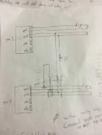 29.7 KB Views: 19
- 6,863
- 707
- 113
- Location
- Stratford/Connecticut
The larger tq gens have connectors for synch cable between the two. Do your gens have the connections?
- 2,606
- 2,354
- 113
- Location
- Efland, NC
That won't work the way you want. To do that right you need VRs with external biasing. PLUS...
That won't fix the circulating currents. Your problem is with the governors on the generators. Not the voltage regulators. Difference in torque from each engine is the source of the circulating current.
That won't fix the circulating currents. Your problem is with the governors on the generators. Not the voltage regulators. Difference in torque from each engine is the source of the circulating current.
- 18,139
- 27,256
- 113
- Location
- Burgkunstadt, Germany
The military never felt the need, nor could anyone ever justify the need, to parallel two small gen sets. Biggest reason, was cost. Why install the circuitry to parallel when no one would ever use it. The mind set in the military was and is, get a bigger set. Need more power, get a bigger set! When the "planners" sit down to figure what a military unit's power requirements are, they ALWAYS choose a larger gen set then they really need. They always have and always will do it that way.
You can only effectively parallel sets that are "Precise Power" gen sets. That makes the set, bigger, heavier, more complicated and drives up the cost. Precise set are very rare in the army. The only ones I ever saw, were mainly in the Air Defence Artillery. There were others, but only a few. Lots of folks talk about paralleling army gen sets, few have actually done it. The only paralleling setup that I ever saw work right consistently, was the PATRIOT missile systems EPP-2 and EPP-3, (150 KW Power Plant). Both the EPP-2 and EPP-3 were designed to run full time in parallel, (Load Sharing) and not just for load switching.
Is it really worth it for you to do this? Or maybe better to find something already set up to work for your application?
Dieselfumes
New member
- 3
- 0
- 0
- Location
- Central Florida
Thank you for the replies but it appears that my original question remains unanswered. Can one 802 VR power two 802 fields without smoking it's internals?
To Suprman; No these do not have any OEM synch cable provisions. I wonder if those sets were inverter gennys. Those are apparently very easy for the mfg to design as parallel-able. If that's even a word.
To Diesel addict; I believe, in layman's terms, external biasing is basically the ability to send a completely isolated signal to each head. I agree that that would be ideal but because these heads are theoretically "identical", the difference in field excitation inputs to match the outputs should be attainable with a slight trimming (adjustable resistance of the potentiometer). As to the governors causing the circulating currents, I respectfully disagree. Once the phase angle indicator(fancy word for 240V panel mount LED) goes out and I close the second output contactor, the stators are now electrically coupled. Maybe not as tightly as a mechanical coupling but not far behind. Enough to make the gen turn the engine if it runs out of fuel, anyway. Circulating current implies current/ voltage going back and forth. If one governor is set way lower than the other, it would be as if that slower prime (engine in the slower unit) was out of fuel and contributing no effort to the spinning party. The current would no longer be circulating, it would be only going in one direction, from the faster prime to the slower prime trying to maintain the faster prime's gov setting. This, to me, is how you can load share between the two. Want one to pull more weight? increase the governor setting. To me, the circulating current is more likely caused by one regulator trying to maintain 120V at the bus while the other is trying to maintain 119V at the bus. I say this because the more meticulous I am with with the voltage setting on each gen before synching, the longer it takes for no load circulating currents to build. Heck, the first time I tried paralleling the two, they both sat there running beautifully with no current showing on either ammeter for the entire 10 minutes with no load. It wasn't until I put load on it that the VR's reacted ever so slightly out of synch to produce a circulating current that overloaded the gens. Again, I'm not trying to argue, just respectfully disagree.
To guyfang; Lol. Cost seems to be one of the last considerations for the military (and rightly so). Reliability is more likely. Heck, they don't care if they wet stack an 803 by powering a phone charger for days on end. They just put it on GL and grab a new one. Lol. I don't have that luxury. So to me, it is worth it if I can do it. These 802's I have are perfect for me. I got a smokin deal on the set ($2100 including the trailer) and they both run perfect.
I only have a vague idea on electrical theory and I'm obviously not an engineer, but I am pretty good at draggin things back to my cave, figuring out how they work, why they break, and how to make them work better for me. Put it this way, this is going to happen. If I'm wrong and it smokes my rig(s), I will have mapped out the perfect path to utter paralleling failure, other tinkerers like myself can learn from my mistake (maybe), and you can all give me the self-gratifying "I TOLD YOU SO". Lol. If it does work, I will leave my cave in search of my next project to make something do what it wasn't designed to do. Most importantly, please do not take offense to my thick-headed approach. I'm wrong more than half the time when it comes to reverse-engineering electronics but every once in a while I'm right. Just enough to make me keep trying. Lol. As always, I am looking forward to finding out which one it is this time as well.
Dieselfumes
New member
- 3
- 0
- 0
- Location
- Central Florida
****. I didn't proof my reply. I said the stators would be coupled. Meant to say rotors. No point coupling something that's not moving. Lol.
- 2,606
- 2,354
- 113
- Location
- Efland, NC
Ok. You are right based on your description. Your voltage regulators are not playing nice together.
Driving both from one regulator is likely going to damage the regulator. I don't recommend doing that.
Since you are determined to parallel the generators I would recommend setting them each up on a load bank and nulling out the voltage regulators. Make them react to load the same way. Then you will be able to parallel them with minimal circulating current.
I'm going to see if I can find the info on the adjustments on the regulator board to point you in the right direction.
Korgoth1
New member
- 191
- 6
- 0
- Location
- radford, va
I would say no, the vr on these is barely enough for one set(why the quad fuse is necessary)
- 2,606
- 2,354
- 113
- Location
- Efland, NC
The info you need on the VR board isn't in the standard TMs.
The following are my thoughts on how I would do it. I offer these thoughts with zero guarantee of success and zero guarantee of not blowing it all up (or worse, hurting yourself). It is possible to seriously injure yourself and destroy the equipment if you decide to try this. The risk is yours to take. I recommend against doing it.
To minimize circulating current the VR needs to maintain similar voltages on each generator as load increases. This is done by adjusting the DOOP of the VR. The DROOP adjustment will be via a POT on the VR board. I don't have one here to look at so I can't give you any insight as to which one it is. If one is labeled DROOP then that would be the one.")
What you don't want to do is to try and adjust things so the voltage remains constant as load is applied. The voltage should be allowed to sag a little. The trick is getting both generators to sag the same amount.
The first step is to characterize the operation of each generator. Step load each generator with a resistive load bank (I use water heater elements in water) and carefully measure the voltage at each at each load step. This is one case where resistive load is your friend. It will make the adjustments easier. The more load steps the better picture of the voltage droop curve (and the differences between them) you'll get. If you see differences between the generators from this test you stand a reasonable chance of making some adjustments and having things work. At a minimum you need 3 load points with one being near 100%. 0% doesn't count.
For the load bank get a couple of 2500w elements and a 3500w element. You can use them in different combinations of series and parallel to get different load points. One 2500w is 2500w. Two 2500w in parallel is 5000w. Two 2500w in series is 1250w. A 3500w and a 2500w in parallel is.. I think you should get the picture here.
It is very important to know that you are loading the generators the same way during the test. Use an accurate voltage meter and amp meter. Being precise is important.
Once you have the numbers, choose one generator (and its voltage numbers) to be the master and tweak the other generators VR to match it as closely as you can using the DROOP pot on the board. After any adjustment is made you need to go back through all the loads again and record the values. To simplify things you can start with a light load (1250w) and a high load (6000w) to do your coarse adjustment. Then move to smaller steps to verify linearity and tweak it a bit more if necessary.
After you have the VRs set for similar droop set the generators up for parallel operation and see if that takes care of the circulating current.
The following are my thoughts on how I would do it. I offer these thoughts with zero guarantee of success and zero guarantee of not blowing it all up (or worse, hurting yourself). It is possible to seriously injure yourself and destroy the equipment if you decide to try this. The risk is yours to take. I recommend against doing it.
To minimize circulating current the VR needs to maintain similar voltages on each generator as load increases. This is done by adjusting the DOOP of the VR. The DROOP adjustment will be via a POT on the VR board. I don't have one here to look at so I can't give you any insight as to which one it is. If one is labeled DROOP then that would be the one.
What you don't want to do is to try and adjust things so the voltage remains constant as load is applied. The voltage should be allowed to sag a little. The trick is getting both generators to sag the same amount.
The first step is to characterize the operation of each generator. Step load each generator with a resistive load bank (I use water heater elements in water) and carefully measure the voltage at each at each load step. This is one case where resistive load is your friend. It will make the adjustments easier. The more load steps the better picture of the voltage droop curve (and the differences between them) you'll get. If you see differences between the generators from this test you stand a reasonable chance of making some adjustments and having things work. At a minimum you need 3 load points with one being near 100%. 0% doesn't count.
For the load bank get a couple of 2500w elements and a 3500w element. You can use them in different combinations of series and parallel to get different load points. One 2500w is 2500w. Two 2500w in parallel is 5000w. Two 2500w in series is 1250w. A 3500w and a 2500w in parallel is.. I think you should get the picture here.
It is very important to know that you are loading the generators the same way during the test. Use an accurate voltage meter and amp meter. Being precise is important.
Once you have the numbers, choose one generator (and its voltage numbers) to be the master and tweak the other generators VR to match it as closely as you can using the DROOP pot on the board. After any adjustment is made you need to go back through all the loads again and record the values. To simplify things you can start with a light load (1250w) and a high load (6000w) to do your coarse adjustment. Then move to smaller steps to verify linearity and tweak it a bit more if necessary.
After you have the VRs set for similar droop set the generators up for parallel operation and see if that takes care of the circulating current.
Brock Stetson
New member
- 4
- 0
- 0
- Location
- Ainsworth NE
My MEP 804B gensets come with a port to plug in a Paralleling cord.
Is this a plug and play situation, or is rocket science involved?
And where would I find the parallellng cord?
Thank You for your thoughts
Is this a plug and play situation, or is rocket science involved?
And where would I find the parallellng cord?
Thank You for your thoughts
uniquify
Active member
- 235
- 236
- 43
- Location
- Sioux Falls, SD
Have you tried looking on ebay for a MEP generator parallel cable?My MEP 804B gensets come with a port to plug in a Paralleling cord.
Is this a plug and play situation, or is rocket science involved?
And where would I find the paralleling cord?
Thank You for your thoughts
Also, you might have better luck by starting a new thread.
- 18,139
- 27,256
- 113
- Location
- Burgkunstadt, Germany
You might have gotten more help if you had started a new thread.My MEP 804B gensets come with a port to plug in a Paralleling cord.
Is this a plug and play situation, or is rocket science involved?
And where would I find the parallellng cord?
Thank You for your thoughts
Read the book. The paralleling operation is simple. Its a matter of hooking up the cable, and reading the book. The cable should have been in in the sets. Check flbay, send Suprman a mail, he should have a few. READ THE BOOK. Its simple, but you can cause damage if you improperly attempt the operation.
Brock Stetson
New member
- 4
- 0
- 0
- Location
- Ainsworth NE
Thank you Uniquify!Have you tried looking on ebay for a MEP generator parallel cable?
Also, you might have better luck by starting a new thread.
I have seen the cables at a reasonable price somewhere - I will look on ebay.
I will try starting a new thread.
I just started (writing) on this sight - so how to start a new thread is not obvious, but I shall learn.
Thanks Again!
Brock Stetson
New member
- 4
- 0
- 0
- Location
- Ainsworth NE
Thank You Guyfang!
I have found several good online books through this site. But please tell me what Book I am looking for? I do not have a physical book.
I am pleased to know the system is simple. That is great news.
And I will be very cautious I have heard many horror stories of people not respecting generators.
I am new, so this site is not obvious to me. But I will try to start a new thread and track down Suprman as suggested.
Thanks again.
- 18,139
- 27,256
- 113
- Location
- Burgkunstadt, Germany
In the SS TM forum, is all the manuals needed to use, and work on the gen set. The instructions on the operation of the set is in TM 9-6115-643-10. Go to page, (PDF reader page number) 61. The instructions start there.
Brock Stetson
New member
- 4
- 0
- 0
- Location
- Ainsworth NE
OK Guyfang - I'm tracking that down now. Thank You!
I'm on it thank you Guyfang!
I'm on it thank you Guyfang!
In the SS TM forum, is all the manuals needed to use, and work on the gen set. The instructions on the operation of the set is in TM 9-6115-643-10. Go to page, (PDF reader page number) 61. The instructions start there.
- 114,263members
- 167,173threads
- 2,353,593posts
- 7,880online users