-
Steel Soldiers now has a few new forums, read more about it at: New Munitions Forums!
CUCV alternator symptoms, diagnosis and fix.
- Thread starter Barrman
- Start date

- Status
- Not open for further replies.
More options
Who Replied?badassissimo
New member
- 236
- 1
- 0
- Location
- Iowa, la
I had seen that thread a while back. I had thought about it but I'd rather have the dual voltage.
Too bad cucv electric isn't selling. That's where I got my rebuild kits. As far as I know, its been a great aide to me. Well priced too.
Too bad cucv electric isn't selling. That's where I got my rebuild kits. As far as I know, its been a great aide to me. Well priced too.
- 1,229
- 53
- 48
- Location
- S.E. WI & S.E. TN, USA - Earth
I found out this evening that I need to rebuild my passenger side Alt. I will be doing both while I'm at it.
I've read allot of these threads and need to know who's selling the kits now.
Bert
I've read allot of these threads and need to know who's selling the kits now.
Bert
Last edited:
skysix
Member
- 334
- 0
- 16
Ugh. Some "fun" today - gauge started reading well into the red then a insulation-ish smell. Left running and popped the hood - rear battery was venting gas and boiling. So I'm assuming it is cooked (yeah I know - bad pun) So what would cause that sort of voltage runaway?
skysix
Member
- 334
- 0
- 16
the finned thing?
No the voltage regulator is the white item with three mounting holes in it and and the two plug terminals. The finned thing is the voltage rectifier
No the voltage regulator is the white item with three mounting holes in it and and the two plug terminals. The finned thing is the voltage rectifier
Last edited by a moderator:
Durango_USMC
Member
- 663
- 0
- 18
- Location
- Indianapolis, IN

 Well after reading this thread and the TM as well as doing a search I still have a question or two and a few opinions I need verified.
I have a GEN2 and voltmeter issue on my M1008. The Gen 2 light doesnt come on like the Gen 1 does and the voltmeter reads zero and doesnt move at all. The fuse was also blown.
I have replaced the fuse but the issues remain. Previous owner states he put in a working voltmeter before he sold it to me but could never get it to work right. The batteries still hold a charge and the alternator is still putting out power in the appropriate voltage.
So after poking around in the engine bay on the back of Gen2 there is a stud Ill post pictures if I can, that has an orange wire and red wire attached to it. The orange wire is holding on by a few strands and the nut as well as the wire eyelets are frozen to the stud, the stud however turns freely in its hole. Furthermore the plug on the top of the alternator seems pretty crispy... Im going to try to clean it out when I can then replace if cleaning fails.
But my questions are:
Does the broken orange wire and crispy looking plug create my gen 2 and voltmeter issues?
Because the nut and wires are frozen to the stud but the stud moves, is it ok for me to remove the stud to get the wires off or is it connected to anything inside the alternator that would come loose if unscrewed?
Any other suggestions?
Last edited:
The orange wire is only used for the STE/ICE diagnostic system. Not needed. The plug DOES need to be clean and make good contact for the alternator to work.
You can replace it for under $5.
Disconnect your batteries before replacing it. The red lead is live with 24v. Sparks can fly.
You can replace it for under $5.
Disconnect your batteries before replacing it. The red lead is live with 24v. Sparks can fly.
Durango_USMC
Member
- 663
- 0
- 18
- Location
- Indianapolis, IN
I'll clean it out when I get off and if that doesnt work I'll grab a new plug in the morning. Is that stud suppossed to be loose though? Also there is a red ring around it that appears to be cracked and broken up if that means anything. Thanks again.
Semper Fidelis
Semper Fidelis
skysix
Member
- 334
- 0
- 16
Well after reading this thread and the TM as well as doing a search and reading some other threads I still have a question or two and some information I couldn't find.
Same issues as Durango USMC. Replaced both voltage regulators with HD ones, both stators with HD (200A nominal) versions, both rotors (the pax side rotor was bad), both diode trios checked out OK. Testing the plug wires (brown and red) on both alternators was 12 and 24 v both with key on and off
I get 12.5V off the rear battery (running) so I know Alt 2 is not charging now (after the rebuild I was getting 140A and 29.0V off the pax side alternators voltage regulator running (briefly, like for a day or so) and with the Gen 2 lamp working but no voltmeter. Also was getting 13.8V (running) off the drivers battery and 14.2V and 145A off the drivers side alternators voltage regulator.
Measured 13.4V at the dash voltmeter (which doesn't budge AT ALL from hard left) and the Gen 2 light is currently INOP. Batteries load test at 350A (front) and 400A (rear) = group 31 950 CCA rated Autozone Duralast.
All fuses in the fuse panel are OK, Bulb filament is intact – and was working earlier, all fusible links are conducting test meter voltages/current, good connection through the plug on the back of the alternator.
The Diode I am not sure about - get between 50 and 190 ohm one way (with the neg probe at the banded end) very briefly before the (digital) multimeter shows a 1 – the same as when nothing is under test. In the other direction it never changes from a 1. Diode is marked as a Motorola W 058G 8609.
Will get some contact cleaner and dialectric grease tomorrow and retest – contacts look good though.
What plug contact has the thin red circle in the picture?
And where is the relay located?
- 34,010
- 1,827
- 113
- Location
- GA Mountains
Gen 2 relay is under the dash near the starter relay that is often upgraded.
The stud in not suppost to turn. If it shorts to the case then fireworks will follow. That will be a direct short. Time to take your alternator apart and rebuild it.I'll clean it out when I get off and if that doesnt work I'll grab a new plug in the morning. Is that stud suppossed to be loose though? Also there is a red ring around it that appears to be cracked and broken up if that means anything. Thanks again.
Semper Fidelis
skysix
Member
- 334
- 0
- 16
there are two there - any idea which?Gen 2 relay is under the dash near the starter relay that is often upgraded.
The GEN2 relay and the Voltmeter relay look identical. They are mounted to the bracket along with the starter relay. They could be in either hole.
The wiring colors are the same. So you just have to do some testing and maybe switching of the relays. Sorry.
Might be a good idea to label which is which for future reference
The wiring colors are the same. So you just have to do some testing and maybe switching of the relays. Sorry.
Might be a good idea to label which is which for future reference
Durango_USMC
Member
- 663
- 0
- 18
- Location
- Indianapolis, IN


Ouch... I knew this would be painful. But thank you none the less.The stud in not suppost to turn. If it shorts to the case then fireworks will follow. That will be a direct short. Time to take your alternator apart and rebuild it.
EDIT: To add...
I think I figured out the actual problem with Gen 2 and the voltmeter... should there be a brown wire here? Ive attached a picture of all the wires that were attached to Gen2 and me pointing where I think a wire is suppossed to be. Also it appears the stud doesnt freely turn its actually just wiggling in the gap created by the half disintegrated isolator washer.
Last edited:
skysix
Member
- 334
- 0
- 16
both relays good. Upgraded to 80amp for future. Bulb tested and good. Having a hard time finding a new diode...
Now the VM itself - when I remove the bulb and look inside there appear to be 2 small solder tipped copper tabs - is there supposed to be a shunt there or something? Needle still will not move when connected to the 24v buss and ground...multimeter reads 13.4v however with the engine running.
Now the VM itself - when I remove the bulb and look inside there appear to be 2 small solder tipped copper tabs - is there supposed to be a shunt there or something? Needle still will not move when connected to the 24v buss and ground...multimeter reads 13.4v however with the engine running.
Attachments
-
 65 KB Views: 100
 -
 82.1 KB Views: 84
Last edited:
The voltmeter on the CUCV is actually a 12v version. There is a 300ohm resistor added to the back on the meter to make it work as a 24v unit. This resistor is the white flat ceramic unit. I don't know if anyone ever found a replacement, but many members has built their own with Radio Shack resistors. Been document many times.
As far as the GEN bulbs. Because the voltage is different (12v vs 24v) the wattage of the bulbs are different. GEN1 - type 168 5 watt, GEN2 - type 194 3 watt. While both will work, the brightness will be different.
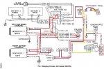
As far as the relay circuit. You missed the "splice" connection for the circuit. Here is the path:
1 - from diagram E/F-4, with the key on, circuit 139A is hot,
2 - power goes to the "splice" and feeds circuit 139G and 139F
3 - circuit 139F feeds the Voltmeter relay coil
4 - circuit 139G feeds the GEN2 relay coil
5 - both relays are continuely grounded.
6 - clear as mud?
As far as the GEN bulbs. Because the voltage is different (12v vs 24v) the wattage of the bulbs are different. GEN1 - type 168 5 watt, GEN2 - type 194 3 watt. While both will work, the brightness will be different.
As far as the relay circuit. You missed the "splice" connection for the circuit. Here is the path:
1 - from diagram E/F-4, with the key on, circuit 139A is hot,
2 - power goes to the "splice" and feeds circuit 139G and 139F
3 - circuit 139F feeds the Voltmeter relay coil
4 - circuit 139G feeds the GEN2 relay coil
5 - both relays are continuely grounded.
6 - clear as mud?
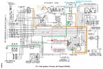
That terminal is only used on GEN1. It is the feed for the tach buffer. Only used with the STE/ICE diagnostic system. GEN2 would have a rubber cap on it from the factory. The cap has been lost on most trucks over the years.View attachment 425562
I think I figured out the actual problem with Gen 2 and the voltmeter... should there be a brown wire here? Ive attached a picture of all the wires that were attached to Gen2 and me pointing where I think a wire is suppossed to be. Also it appears the stud doesnt freely turn its actually just wiggling in the gap created by the half disintegrated isolator washer.
The red plastic piece needs to be replaced. Only way to do that is to take the alternator apart. Might as well rebuild it while it is apart (unless you have done it recently).
- Status
- Not open for further replies.
- 114,408members
- 167,301threads
- 2,355,083posts
- 1,495online users