Barrman
Well-known member
- 5,478
- 2,223
- 113
- Location
- Giddings, Texas
I am new to the CUCV world. Not the MV world or this site though. I have been reading for years about CUCV starter, glow plug and alternator troubles. So much that I was really hesitant to get one for myself. So, now that I have one I want to pass on a few things I have learned about the charging system to maybe help others.
Our resident CUCV wiring expert, Warthog, assembled my M1009 out of 3 or 4 donors. The wires were all cut off for the alternators and the alternators were not on the truck. One of the reasons I got the truck was that he had new or rebuilt ones on it. I get it home and realize ALT 2 isn't charging.
Now, having read about 20 post a day for the past 5 years about CUCV alternators. I "knew" if the red ALT 2 light wasn't coming on before engine start, the bulb must be burned up which causes the alternator to not work. Mine wasn't coming on, ever, so that must be the problem. I got the truck with no dash or cover on it. I of course didn't figure out the alternator wasn't working until I installed all that stuff.
I called up Joe. He told me to do what I would have done with any other vehicle besides a CUCV. Check voltage at the alternator with the key off and with the key on.
Each alternator is a 12 Volt unit. The big red wire that is bolted on has 12 volts from the battery. The little white plug has 2 wires on it. The thicker is the voltage out of the alternator back to the battery. The smaller wire is the exciter wire.
With the engine off, the big red wire should have battery voltage, so should the bigger wire on the plug and with the plug off, key off, the exciter wire should have nothing.
Turn the key on and the plug off, the exciter wire will have battery voltage along with the other 2.
The above should be your first check of a suspected bad alternator. This tells you if the problem is in the alternator or in the truck. After making sure all wires are hooked up and not grounding out somewhere that is.
My truck side was working properly. I had a problem in the alternator. I called Joe up and asked about the red ALT 2 light. I "knew" it had to be part of the problem because I had read about it here on SS for so long. He kept telling me to ignore the red light. I kept telling him I couldn't, even though it didn't make sense. He told me to look up the -30 procedures for testing the alternator inards and to replace what is bad.
I pulled the alternator off, looked up stuff in the -34 and was lost. They wanted me to build a variable voltage machine just to check out the voltage regulator. I don't have a variable voltage source, so I just threw in a known good regulator and put it back on the truck. I didn't turn the page in the manual to check out all the other components. I took care of the first thing listed in the manual.
The alternator didn't work and the silly ALT 2 light still wasn't coming on. I just knew that ALT 2 light was part of the problem in some way. I still drove the truck though.
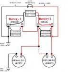
Maybe I should cover how you can drive a truck around with a bad alternator and it not be a problem. CUCV's are 12 volt Chevy trucks at heart. The wire for the engine to run, the lights, the blinkers and all that are all 12 volt. The drivers side alternator, ALT1, runs that part of the truck along with the front battery. As long as ALT 1 is good, the truck will drive until you run out of fuel.
The passenger side alternator, ALT 2, only has to charge the rear battery up after the truck has been started. The starter is the only part of the truck that uses the rear battery. I had probably 30 starts on the truck without the battery getting charged. The volt meter was at the top of the yellow zone and the starter turned over at the same speed every time. That was 2 weeks of in town driving without ALT 2.
Since I didn't have the variable voltage thingy machine to test out the alternator, I broke down and paid $44.50 for a complete 27si rebuild kit. All new everything inside the alternator. I put it on and turned on the key. The ALT 2 light lit up. I fired up the engine and the voltage gauge was in the green for the first time since I bought the truck. A volt meter at each battery showed 14.4 and 28.8 across both. It was working.
But, what was wrong? I still had a suspicion that I had hit the dash or something making the light come on and therefore the entire system work. Even though Joe and my test showed the trouble was in the alternator.
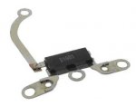
I put all the parts I pulled off in a bag and went looking on the Delco Remy site for their version of a test. I posted a thread about the manuals there. They word the test different and I actually turned the page. The Diode Trio and the rectifier bridge can both be tested with a simple Ohm meter. I put new of each in the alternator.
I got out an Ohm meter and tested the Diode Trio I had removed from the alternator. Very simple instructions. Put one lead on the long leg and the other lead on any of the 3 shorter legs. Look at what you get and then switch the leads. One way should be high and the other low. If they are the same, the Diode Trio is bad. My just removed Diode Trio had the same value on all 3 legs with the leads reversed. Bad Diode Trio.
The test for the rectifier bridge is the exact same thing on it. Mine was good.
If you have read this far, you get the summary.
If you are not getting voltage out of an alternator, no light before start up or during running, the exciter wire is exciting and all the other wires are correct. Then I would suggest you spend the $4.00 or so for a new Diode Trio for a 27-si alternator, put it in and go find something else to work on. Or at least read all the pages about testing the alternator parts, test them and then figure out what is bad.
Our resident CUCV wiring expert, Warthog, assembled my M1009 out of 3 or 4 donors. The wires were all cut off for the alternators and the alternators were not on the truck. One of the reasons I got the truck was that he had new or rebuilt ones on it. I get it home and realize ALT 2 isn't charging.
Now, having read about 20 post a day for the past 5 years about CUCV alternators. I "knew" if the red ALT 2 light wasn't coming on before engine start, the bulb must be burned up which causes the alternator to not work. Mine wasn't coming on, ever, so that must be the problem. I got the truck with no dash or cover on it. I of course didn't figure out the alternator wasn't working until I installed all that stuff.
I called up Joe. He told me to do what I would have done with any other vehicle besides a CUCV. Check voltage at the alternator with the key off and with the key on.
Each alternator is a 12 Volt unit. The big red wire that is bolted on has 12 volts from the battery. The little white plug has 2 wires on it. The thicker is the voltage out of the alternator back to the battery. The smaller wire is the exciter wire.
With the engine off, the big red wire should have battery voltage, so should the bigger wire on the plug and with the plug off, key off, the exciter wire should have nothing.
Turn the key on and the plug off, the exciter wire will have battery voltage along with the other 2.
The above should be your first check of a suspected bad alternator. This tells you if the problem is in the alternator or in the truck. After making sure all wires are hooked up and not grounding out somewhere that is.
My truck side was working properly. I had a problem in the alternator. I called Joe up and asked about the red ALT 2 light. I "knew" it had to be part of the problem because I had read about it here on SS for so long. He kept telling me to ignore the red light. I kept telling him I couldn't, even though it didn't make sense. He told me to look up the -30 procedures for testing the alternator inards and to replace what is bad.
I pulled the alternator off, looked up stuff in the -34 and was lost. They wanted me to build a variable voltage machine just to check out the voltage regulator. I don't have a variable voltage source, so I just threw in a known good regulator and put it back on the truck. I didn't turn the page in the manual to check out all the other components. I took care of the first thing listed in the manual.
The alternator didn't work and the silly ALT 2 light still wasn't coming on. I just knew that ALT 2 light was part of the problem in some way. I still drove the truck though.
Maybe I should cover how you can drive a truck around with a bad alternator and it not be a problem. CUCV's are 12 volt Chevy trucks at heart. The wire for the engine to run, the lights, the blinkers and all that are all 12 volt. The drivers side alternator, ALT1, runs that part of the truck along with the front battery. As long as ALT 1 is good, the truck will drive until you run out of fuel.
The passenger side alternator, ALT 2, only has to charge the rear battery up after the truck has been started. The starter is the only part of the truck that uses the rear battery. I had probably 30 starts on the truck without the battery getting charged. The volt meter was at the top of the yellow zone and the starter turned over at the same speed every time. That was 2 weeks of in town driving without ALT 2.
Since I didn't have the variable voltage thingy machine to test out the alternator, I broke down and paid $44.50 for a complete 27si rebuild kit. All new everything inside the alternator. I put it on and turned on the key. The ALT 2 light lit up. I fired up the engine and the voltage gauge was in the green for the first time since I bought the truck. A volt meter at each battery showed 14.4 and 28.8 across both. It was working.
But, what was wrong? I still had a suspicion that I had hit the dash or something making the light come on and therefore the entire system work. Even though Joe and my test showed the trouble was in the alternator.
I put all the parts I pulled off in a bag and went looking on the Delco Remy site for their version of a test. I posted a thread about the manuals there. They word the test different and I actually turned the page. The Diode Trio and the rectifier bridge can both be tested with a simple Ohm meter. I put new of each in the alternator.
I got out an Ohm meter and tested the Diode Trio I had removed from the alternator. Very simple instructions. Put one lead on the long leg and the other lead on any of the 3 shorter legs. Look at what you get and then switch the leads. One way should be high and the other low. If they are the same, the Diode Trio is bad. My just removed Diode Trio had the same value on all 3 legs with the leads reversed. Bad Diode Trio.
The test for the rectifier bridge is the exact same thing on it. Mine was good.
If you have read this far, you get the summary.
If you are not getting voltage out of an alternator, no light before start up or during running, the exciter wire is exciting and all the other wires are correct. Then I would suggest you spend the $4.00 or so for a new Diode Trio for a 27-si alternator, put it in and go find something else to work on. Or at least read all the pages about testing the alternator parts, test them and then figure out what is bad.
Last edited: