• Steel Soldiers now has a few new forums, read more about it at: New Munitions Forums!

  • Microsoft MSN, Live, Hotmail, Outlook email users may not be receiving emails. We are working to resolve this issue. Please add support@steelsoldiers.com to your trusted contacts.


cucv glow plug card

sloride66

New member
9
0
0
Location
Haymarket, VA
Well,
My parts arrived from FLMV today, I was impressed since I ordered them yesterday. My controller board was absent when I picked up this M1009. I popped in the new controller board into the empty cigarette pack sized socket under the dash and installed the socket end cover. I then tucked everthing up under dash and said one Act of Contrition and 2 Hail Marys. I turned the key to on and watched all the lights come on with buzzer. The wait to start light went out after about 10 seconds and I turned the key.....and....wait for it...... BOOM! Ignition on the first revolution of the crankshaft. She smoked at both exhausts and squalled the belts for about a minute and then quieted down into a nice fast idle. I am a very happy camper!:razz: 2 minutes later idle goes to normal and I listen to purr of a 24 year old 6.2. The thing is a bit quieter than my '99 Cummins Dodge. It is about 20 degrees F here.
Important info- The board was packaged in a GM original parts bag along with a new socket and short harness witch includes a new "wait to start bulb and a connector to tie into the OEM harness. I will save this part for future use if needed by myself or others. The GM Part # on the bag is 12039308. (Obsolete part #) Other part #'s like 12496078 may also be valid but this one fits perfectly and works! $150 aint cheap but I like the idea that it will cycle glowplugs as needed for the required amount of time. Go see FLMV.net if you need parts for CUCV and other MV's. GM emailed the 12496078 as fitting 85-91 6.2 Blazers. I do not know if this is valid or not for 24V CUCV's also. Other's here probably can answer that question.


Thanks to those who confirmed my suspicions!
 
Last edited:

allrevup

Member
271
2
18
Location
Delaware
If you look on Ebay just today there are 2 listed, One NOS #2920-01-219-7842 The other one is a used one . I have lost the whereabouts info for a guy that refurbiches then and list then in ebay I belive the stores or his ebay name was Jersey4x4, GOOD LUCK
 

tjmilitary

Member
222
2
16
Location
Grant Park,IL
No one has said if there is something I should look for to be wrong before I put in a new card. Any sugestions from anyone or just try a different card. Thanks for the help.
 

m38inmaine

Well-known member
2,090
45
48
Location
Maine USA
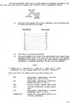
Go to the resource section, download TM 9-2320-289-20, find page 2-62 and read, it tells you how to check the glow plug card circuit before replacing the card.
 

tjmilitary

Member
222
2
16
Location
Grant Park,IL
I ran the test you said to do before installing the new card. Looks like the gp switch is bad and also the purple wire should have 12v but only has 8-9v. Anyone know what this means?
 

allrevup

Member
271
2
18
Location
Delaware
Well,
My parts arrived from FLMV today, I was impressed since I ordered them yesterday. My controller board was absent when I picked up this M1009. I popped in the new controller board into the empty cigarette pack sized socket under the dash and installed the socket end cover. I then tucked everthing up under dash and said one Act of Contrition and 2 Hail Marys. I turned the key to on and watched all the lights come on with buzzer. The wait to start light went out after about 10 seconds and I turned the key.....and....wait for it...... BOOM! Ignition on the first revolution of the crankshaft. She smoked at both exhausts and squalled the belts for about a minute and then quieted down into a nice fast idle. I am a very happy camper!:razz: 2 minutes later idle goes to normal and I listen to purr of a 24 year old 6.2. The thing is a bit quieter than my '99 Cummins Dodge. It is about 20 degrees F here.
Important info- The board was packaged in a GM original parts bag along with a new socket and short harness witch includes a new "wait to start bulb and a connector to tie into the OEM harness. I will save this part for future use if needed by myself or others. The GM Part # on the bag is 12039308. (Obsolete part #) Other part #'s like 12496078 may also be valid but this one fits perfectly and works! $150 aint cheap but I like the idea that it will cycle glowplugs as needed for the required amount of time. Go see FLMV.net if you need parts for CUCV and other MV's. GM emailed the 12496078as fitting 85-91 6.2 Blazers. I do not know if this is valid or not for 24V CUCV's also. Other's here probably can answer that question.


I have to replace my AC 13g's Glow plugs =readily available. I have used the Wellman's G070 and IMO do not think that they are different or better, both with 1 year warranty.

If this new "Control Cards" can be used in the CIVILIAN Blazers.
I thought they all use the under hood controllers ?
Can someone elaborate on this.

But If this NEW replacements cards can also be used in the '85-'91 6.2 Blazer, witch are using the self regulating AC Delco 60g Glow plugs or The Wellman's #G0050 (both with one year warranty) they could also use Bosch Duraterm Premium #BS80034 (with 3 years warranty)

Is it possible to use this Glow Plugs with the NEW card, with out the Manual switch for longer cycles in the CUCV ?
 

mr.travo

Member
422
0
16
Location
Comfort, TX
Ok....

Few questions on here. I know until you learn the system the CUCV glow plug system is a nightmare. I am still learning and need to pick some brains.

I have the manual and without some pics (yes I am an Infantryman) I am having a hard time understanding what some of these things are.

The problem I have with my system is all the right lights come on and work fine, but the glow plugs don't kick in. There is no clicking from the relays and such. I have to "jump" the connections under the hood (field expedient push button). So, I am tired of popping my hood and doing this each time the truck isn't warmed up.

If someone could break this down to me on the dummy level, I would appreciate it. I guess I learn better by seeing than reading (again, I AM an Infantryman, LOL!).

Thanks guys, as always!

Travo
 
Last edited by a moderator:

Warthog

Moderator
Super Moderator
Steel Soldiers Supporter
13,775
227
63
Location
OKC, OK
A couple of assumptions. The system is 24v and is stock.....................Is the Glow Plug Relay a stock item or a replacement? Is the internal circuit isolated from the housing?

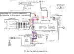
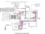
First thing to check is the wiring on the glowplug relay mounted on the firewall.

The red is coming from the resistor pack and is connected to the top lug.

The two large orange wires and the small orange wire are connected to the bottom lug. The wiring diagram shows the small orange wire on the top lug. This is a misprint and must be corrected in order for the GP system to work.

The light blue wire is connected to the one of the small terminals

The pink/black wire is connected to the other small terminal.

Follow the tech manual troubleshooting section "Glow Plug Module Inoperative", Paragraph 15, Page 2-62 of the TM 9-2320-289-20. It covers how to test the controller wiring. It does not cover diagnosing the board itself.

Check these and let us know.
 

Attachments

Last edited:

mr.travo

Member
422
0
16
Location
Comfort, TX
Yes, the system is 24v and stock. The relay is of the newer style (cylinder type). I will double check the wires, but I am pretty sure they are right. It's raining pretty hard outside right now, so I will check once it lets up.

I have read the manual and I get lost when it starts talking about checking any circuit that doesn't operate correctly on the printed circuit board.
 

Warthog

Moderator
Super Moderator
Steel Soldiers Supporter
13,775
227
63
Location
OKC, OK
The section of the manual above is just checking voltage and resistance from the wires to the circuit board. It is not checking the board itself.
 

mr.travo

Member
422
0
16
Location
Comfort, TX
Ok, on the terminal I have the top and bottom post (big wires) are correct. On the two smaller middle posts, I have the black/red wire as the top and the blue(ish) wire the bottom wire. Is this the problem????
 

Warthog

Moderator
Super Moderator
Steel Soldiers Supporter
13,775
227
63
Location
OKC, OK
Ok, on the terminal I have the top and bottom post (big wires) are correct. On the two smaller middle posts, I have the black/red wire as the top and the blue(ish) wire the bottom wire. Is this the problem????
The small wires can be on either post, they energize the relay with 12v. You can test the relay with a 12v jumoer wire if needed.

Where is the small orange wire mounted?

I will post some more test procedures on tuesday.
 

Alredneck

Banned
1,494
15
0
Location
TN
Memphis Equipment sells the cards also, be prepared to pay a arm n leg for em!

We have 5 M1009s from a GSA auction all with the cards removed, was looking for replacements. I dont think I have enough arms n legs for Memphis Equipments parts. I think I will just do the wire and switch deal.
 

Warthog

Moderator
Super Moderator
Steel Soldiers Supporter
13,775
227
63
Location
OKC, OK
...I have to "jump" the connections under the hood (field expedient push button)
Which wires are you jumping?

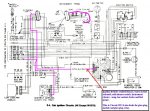
To help you(me) understand the Glow plug circuit - We will start with the relay..................

There are two wires that energize the relay. The PINK/BLACK wire which feeds 12v to the relay and the LIGHT BLUE wire which grounds the relay.


When the key is in the "RUN" posistion, fuse #17-Engine control, is energized.

This feeds the PINK/BLACK circuit #39 (circuits are numbered in the diagrams for tracing only - no numbers are printed on the wires).

Circuit #39 supplies power to: seatbelt buzzer, water-in-fuel solenoid, cold advance switch, instrument cluster bulbs-temp, low coolant, brake and fuel gauge.

It also supplies power to the Glow Plug Module and Glow Plug Relay.

So when the key is in "RUN", 12v should be present at the PINK/BLACK wire.


The LIGHT BLUE wire, Circuit# 505, is the "ground" wire for the relay. To complete the circuit at the Relay, the Glow Plug Controller "connects" the LIGHT BLUE wire to ground (it is part of the integrated circuit and beyond the scope of this discussion). The Controller connect to ground via Circuit #151 - BLACK wire.

By following the troubleshoooting section for the Glow Plug Module, you will be checking for the 12v at the PINK/BLACK wire and by jumping the LIGHT BLUE wire to ground you will be checking the relay.

Right Click on Thumbnail and choose "Open Link in New Window"
 

Attachments

Last edited:
Top
AdBlock Detected

We get it, advertisements are annoying!

Sure, ad-blocking software does a great job at blocking ads, but it also blocks useful features of our website like our supporting vendors. Their ads help keep Steel Soldiers going. Please consider disabling your ad blockers for the site. Thanks!

I've Disabled AdBlock
No Thanks