- 7,032
- 2,695
- 113
- Location
- Montevideo/Uruguay
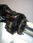
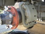
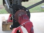
Just saw this last weekend at the Unimog museum in Gaggenau......... disc brakes with TWO calipers on EACH front wheel .....

G.
Attachments
-
 48.1 KB Views: 367
Steel Soldiers now has a few new forums, read more about it at: New Munitions Forums!

Just saw this last weekend at the Unimog museum in Gaggenau......... disc brakes with TWO calipers on EACH front wheel .....
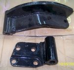
Yep those brackets were cut on a water jet.Looks good do you make the brackets?
Just saw this last weekend at the Unimog museum in Gaggenau...
G.
")
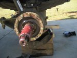
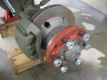
i went out and looked yesterday - i can't find a PN stamped anywhere that is still visible. the rotor pictured sure looks correct, but...Now we need to find the front rotors and start discussing how we might go about making it happen.
Judging from his posts, mudguppy is very happy with his, so if you're impatient or not handy with tools
you might want to save up and buy from the guy at diff eng.
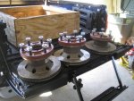
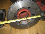
Edit: Believe I've found the front rotors.
Front Rotor info: Rockwell wheel brakes w/ pics - Pirate4x4.Com Bulletin Board
User: DriveTime from Pirate 4x4
Off of front 1994 Ford Truck F700
NAPA Part #: NB 4886056
From NAPA:
Attributes: # of Bolt Holes : 6
Bolt Circle Diameter : 8.75"
Brake Rotor Diameter : 15.39"
Brake Rotor Discard Thickness : 1.42"
Brake Rotor Thickness New : 1.54"
Brake Rotor Type : Disc Brake Rotor Only
Center Hole Diameter : 6.45"
Height : 6.03"
Maximum Lateral Runout : .004"
Mounting Type : Type L - Rotor Only. The Rotor Is Mounted Inboard Of The Hub. The Hub & Rotor Sections Are Bolted Together. Replace The Complete Assembly If Hub Flange Is Bent Or Damaged. See Diagram For More Information.
Vented / Solid : Vented
Really need to find an upgrade for the master cylinder/booster set up too.
Subscribed. Really need to find an upgrade for the master cylinder/booster set up too. Jim
I've started a separate engineering thread for this issue now. Please let's try to use that one to give each topic the attention and clarity it deservesA big ol' hairy PLUS 1
Raybestos 8520 crosses to rotors that look like the first ones.also the part number i always used for the rotors is RAYBESTOS Part # 8520.
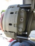

not sure what you mean here - please elaborate since no grinding was required and none of the calipers were 'ground' or machined...... Also, think this was covered but you need to grind the saddle quit a bit on the caliper on the f550. Just info for the at home builder. ...
ill try to find some pics. but you have the f350 calipers in the front if im not mistaken right? The f550 saddle that the caliper mounts to hits the knuckle (on the front) and to get full contact of the brake pad it has to be ground/machined down to allow the pads to make full contact with the rotor. Kylenot sure what you mean here - please elaborate since no grinding was required and none of the calipers were 'ground' or machined...

not sure what you mean here - please elaborate since no grinding was required and none of the calipers were 'ground' or machined...

