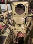
@Buck Wampum - thank you so much for these photos! The coolest thing of all is they come exactly on time - on many occasions I got good reference after it was too late...
And these photos just show how bad the Hobby Boss chassis really is...
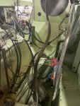
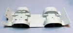
One thing that confirms the feature from the drawing I posted is that the shaft tunnel is not exactly straight, but a little diagonal, so to say.
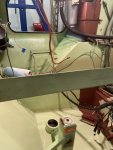
Another surprise for me is the shape of the underside below the engine - I thought the hull bottom there is flat with a cutout for the axle, and your photos show that it's V-shaped with the axle at the point of the V.
I'll see if I can incorporate those features in my model! Thanks again and have a nice day
Paweł
And these photos just show how bad the Hobby Boss chassis really is...
One thing that confirms the feature from the drawing I posted is that the shaft tunnel is not exactly straight, but a little diagonal, so to say.
Another surprise for me is the shape of the underside below the engine - I thought the hull bottom there is flat with a cutout for the axle, and your photos show that it's V-shaped with the axle at the point of the V.
I'll see if I can incorporate those features in my model! Thanks again and have a nice day
Paweł