• Steel Soldiers now has a few new forums, read more about it at: New Munitions Forums!

  • Microsoft MSN, Live, Hotmail, Outlook email users may not be receiving emails. We are working to resolve this issue. Please add support@steelsoldiers.com to your trusted contacts.

M1009 headlight relay installation question

dyocis

New member
85
0
0
Location
Paso Robles, CA
I've read through several threads about people installing aftermarket headlight wiring harnesses and the varying quality and prices.

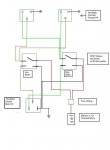
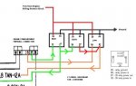
My question is, if I install a set of relays into the stock wiring harness that draws +12v from the engine wiring harness block and uses the stock wiring to the headlights, will it fry the wiring harness? If I do this I will replace the headlight plugs with ceramic connectors to prevent melting.

Also, I will be adding a third relay for the high beam to activate the low beams when high beams are activated.

Is this a bad idea? Do I need to replace the stock wiring with a bigger gauge?

Attached is what I'm planning on doing.


headlight relay closeup.jpg
 

1StumpJumper

Member
173
1
16
Location
NW Washington
If the wiring you are talking about is the stock wiring from the #2 battery to the 12v power distribution terminal, then no,I do not see that it would fry the harness. The power is flowing through the same location in current configuration. Upgrading the size of the wire to the distribution terminal definately would not hurt. I chose to leave that poor wire alone and add an aux fuse panel inside the cab for all new wiring I add. The fuse panel is powered by new wires to the #1 battery.

As far as wiring both circuts to be on at the same time.... I do not know. Could there possibly be an excessive heat build up inside the bulb? Extra load on the ground wire?

I would just do the two relay conversion, call it good after some fuses are wired in, and get some dedicated driving lights to supplement your quest for the bright.
 

Anubis8472

New member
149
3
0
Location
Redford, Michigan
If you're just running the stock headlights then you shouldn't have any issues with the plugs melting.
I replaced mine with ceramic plugs and all new, larger gauge, wiring on the power and ground. The stock wiring on mine now only engages the relays.
I changed out the stock sealed beams for a replaceable bulb style housing and upgraded the bulbs to a higher wattage.
After a while I went back and changed the plugs to ceramic and found one of them had started to melt.

I'm not sure if having the high and low both on with the sealed beam units would generate enough heat to be an issue with the plugs or wiring, but it may be enough to cause your lights to burn out faster.
If you upgrade to the newer/hotter bulbs you'll want to swap out the plugs. If not the ceramic, at least something with more heat resistance.
 

dyocis

New member
85
0
0
Location
Paso Robles, CA
I will be replacing the lights with replaceable bulb housing, and higher wattage bulbs. That was my intention behind upgrading to ceramic plugs. At some point, I may replace with HID bulbs, but I don't want to spend the money on a good set if I don't need them.

I guess since I am replacing the bulb plugs and cutting into the stock wiring anyway, I could just pull the high and low beam wires from the loom and replace them while I'm doing it. It would really only take me 5 or 10 minutes extra and I would have the piece of mind. 12 gauge wires should be plenty from the relays to the ceramic plugs shouldn't it?
 

MarcusOReallyus

Well-known member
4,524
811
113
Location
Virginia
I think you are heading down the wrong road here. Take a look at the commercial upgrade setups - they don't cut into the stock wiring at all. You take MALE fittings to plug into the existing bulb socket, and then you use those to trigger your relays. Power for the headlights now goes from the 12v junction block, via a new wire to your relays, then from your relays to your NEW ceramic bulb socket. (Of course you'll fuse that new wire from the 12v junction block to the relays.)

There's NO modification of the existing plug or wiring, and with the new setup, there's almost no load on them. This keeps your existing wiring intact, so you can always go back very easily if you want to, and reduces the load on them so that they won't burn up. All the heavy current now flows through the new wiring, NONE of it through the old wiring.


OR, you can do like 1StumpJumper did and add your own fuse block tied to the + terminal of the front battery. Let's be clear on the numbering, though:

Battery #1 is the FRONT battery. His positive terminal is where we get our +12v stuff. It goes to the 12v junction block on the firewall.

Battery #2 is the REAR battery. His positive terminal is where we get our +24v stuff.

I think 1Stump called the 12v source the #2 battery, and that's not correct.

Here's a diagram: http://www.steelsoldiers.com/showth...ery-question&p=1305829&viewfull=1#post1305829

Here's the diagram from the TM. Note that Battery #1, the Front battery, has his negative terminal connected to chassis ground. That means his + terminal is 12v above ground.

Battery circuit diagram.jpg
 

MarcusOReallyus

Well-known member
4,524
811
113
Location
Virginia
I've been trying to decipher your diagram, and it's a bit difficult since it's not all there. Can't tell where the wires are all going.

However, I'm pretty sure it's not correct. You should have 4 relays, OR 2 relays, but not 3. You have 4 elements you need to power:


  1. Driver's side high beam
  2. Driver's side low beam
  3. Passenger side high beam
  4. Passenger side low beam

Each of these should have its own relay. (You CAN use one relay for both low beams, and one relay for both high beams.)

You've got 12v correctly going to terminal #30 - that's the one that will come from your 12v junction block OR the + terminal of Battery #1, the front battery. This needs to be fused! 12 or 14 gauge, probably, depending on the current draw of your new headlights.

Also correctly, #85 for all 4 relays goes to a common ground. This is relay coil current only, so 18 gauge is probably fine.

Okay, so Relay #1. His terminal #86 gets switched 12v from the Driver's side high beam contact of the existing driver's side headlight socket. Terminal #87 goes to the Driver's side high beam contact of the NEW driver's side headlight socket. #87A is not used.

And so on with Relays 2, 3, and 4. We take the switching 12v from the existing headlight socket connection to the relay, then the relay output goes to the correct terminal on the NEW headlight socket.

No existing wires are cut. Only relay coil current flows through the old wiring.

Clear as mud? :mrgreen:
 
Last edited:

Skinny

Well-known member
2,130
486
83
Location
Portsmouth, NH
Wouldn't this be the perfect opportunity to tap into the 24v side and use some H4 24v bulbs instead?

Seems like this would remove some load off the front battery and keep the headlights nice and bright...not as succeptable to dimming when idling.

I'm not sure about having both circuits on in one lense. I would be suspect that would be alot of heat. I have cheapo non-DOT (shame on me) Ebay housings with a 35/55 watt (IIRC, OEM wattages) H4 in it. I have no need for any additional ouput on high beams as of now. If anything I would focus on additional driving or fog lighting depending on what you would like to supplement.
 

Warthog

Moderator
Super Moderator
Steel Soldiers Supporter
13,775
227
63
Location
OKC, OK
Here is my rough draft of the LMC harness. The picture of the harness has different ends than the CUCV, but gives you the idea

I was thinking about building some for sale, but my cost just for quality materials alone would be over $50. Not cost effective to make them for sale. Now if you want to make one yourself, you can do MUCH better than the LMC version.
 

Attachments

Last edited:

dyocis

New member
85
0
0
Location
Paso Robles, CA
I'm not worried about keeping my wiring harness stock. I am creating a custom diagram as i modify things. I like a clean install with wires going were they are supposed to. Not spliced in and taped together. That's why i am not buying an aftermarket setup.
 

Anubis8472

New member
149
3
0
Location
Redford, Michigan
I've been trying to decipher your diagram, and it's a bit difficult since it's not all there. Can't tell where the wires are all going.

However, I'm pretty sure it's not correct. You should have 4 relays, OR 2 relays, but not 3. You have 4 elements you need to power:
Yes, he's using one relay for both highbeams, one relay for both lowbeams, the third relay he's using to continue powering the low beams when the high beams are switched on.
That's why there are three in that diagram.

It's been mentioned that running both high/low at the same time may be detrimental to bulb life, but in that diagram, this is what is being done.
 

dyocis

New member
85
0
0
Location
Paso Robles, CA
I guess i didnt say it before, my truck has already been converted to 12v when i got it, and i'm keeping it that way. The first relay is powering both high beams. The second relay is to turn on low beams with the highs, and the third relay is for low only. Since I'm removing the stock headlight wiring and replacing it with 12 guage from the relays on, 1 relay per circuit should be fine. This relay system will be mounted on the fender close to my windsheild wiper motor.
 

Warthog

Moderator
Super Moderator
Steel Soldiers Supporter
13,775
227
63
Location
OKC, OK
So you are using the existing in-cab wiring to control the headlights, removing the engine compartment headlight wiring and replacing with your own wiring.

You are doing exactly what the LMC harness does, but you are deleting the stock engine compartment harness.

Your plan should work just fine.

The stock wiring uses 18ga for the low beam and 16ga for the highbeam. 12ga should be good. With both high/low on at the same time, heat will be an issue and ceramic connectors are a must.
 

dyocis

New member
85
0
0
Location
Paso Robles, CA
So you are using the existing in-cab wiring to control the headlights, removing the engine compartment headlight wiring and replacing with your own wiring.

You are doing exactly what the LMC harness does, but you are deleting the stock engine compartment harness.

Your plan should work just fine.

The stock wiring uses 18ga for the low beam and 16ga for the highbeam. 12ga should be good. With both high/low on at the same time, heat will be an issue and ceramic connectors are a must.
That's exactly what I'm doing, and ceramic connectors are definitely going to be installed. I should have explained my plans a little better in the original post, sorry for the confusion everyone. If bulb life becomes a problem I will either remove the 2nd relay all together, or put a switch on the #2 relay power so I can use it when I choose.

Here is the bigger version of the diagram with the relays labeled.

headlight relay update.jpg
 

1StumpJumper

Member
173
1
16
Location
NW Washington
Marcus- for clarity, I was stating that the stock 12v pos feed comes from the neg terminal of the #2 battery. When I ran new wiring I used the pos terminal of the #1 battery. As you know it is the same voltage , just differnt ends of the companion battery cable.

Sorry for the confusion. It is a moot point here being that dyocis said his rig is already 12v.

Dyocis- please keep us posted in the future on the longevity of your conversion. This is good food for thought. What do you think about adding a switch to the combo relay so you could disconnect if needed. That switch could also power aux driving lights in parallel with the dual beam headlights(via the relay).
 

dyocis

New member
85
0
0
Location
Paso Robles, CA
Dyocis- please keep us posted in the future on the longevity of your conversion. This is good food for thought. What do you think about adding a switch to the combo relay so you could disconnect if needed. That switch could also power aux driving lights in parallel with the dual beam headlights(via the relay).
That is a good idea, and I might add that to the initial installation. There will also be 3 separate fuses for each relay power lead, in case one one relay goes down or blows the fuse I won't lose all my lights at once.

Once I get a final configuration together, I will update my wiring diagram and post it here.
 
Top