I have been planning on adding to this thread for a while and since I'm sick and sidelined on the couch, today is it.
Since this thread is titled in a way that makes it always come up at the top for any M939 winch install, I think we're going to consider it the official "how to install a winch into an M939 series truck" thread and I'm going to add a bunch of stuff here that the OP didn't.
A friend of mine brought me this really clean M931A2 to add a winch to and convert to M932A2 specs. He had a complete takeoff winch kit from an M925 or M925A1. He had already installed the winch w/level winder. I did the rest. Up to this point, I had zero M939 winch knowledge, so I had to learn all of this.
I hope that before folks go out in to the world and buy takeoff winch kits, they read this thread. To be honest, it really makes me mad to see all these people, who are either not knowledgeable, or worse (and more likely), unscrupulous on eBay and all the Facebook pages for military vehicle sales selling kits and saying they fit all M939 models. Really makes me mad. Some poor guy is going to buy a kit that won't work for his model and is going to be halfway through the job before he realizes "oh crap, half my donor it is useless". It takes a lot of self restraint to not post on these people's ads "Hey, you say this fits all models, but it won't fit M932s, any M939A2 model, etc., etc.". The crappy nature of social media would probably just end up with me being flamed anyhoo.
So, the two things you really need to know is that these things are nothing like the older M39/M809 series 5 ton winches or the M44 deuce kits. On the older trucks, you can take a complete winch kit off a wrecker and put it on a dump, etc., etc. They're all the same. These (M939) trucks are not like this, for several reasons. The biggest issue is that the hydraulic tank mounts in a different place on almost every model. The cargo trucks mount on the passenger side, in between the middle tandem and the tool box. The tractors mount it on the drivers side, above the frame, right behind the cab. Dump trucks apparently use the reservoir for the dump hydraulics, which is under the bed, because I never found this model in the TM. Wreckers use the giant 80(?) gallon reservoir that hangs on the side of the hoist for the front winch. Weirdo models like the M934, I have no idea.
Dump (M930) reservoir:
View attachment 657283
Cargo (M925 and I think M92
")
reservoir:
View attachment 657284
Tractor (M932) mount:
View attachment 657285
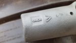
And of course, the hydraulic tank itself is specific, since the brackets are welded on them. So it's now like you could just swap brackets. M925 shown on right, M932 shown on left.
View attachment 657286
Also, beware, on our M925 donor tank, it had a cracked ear from stress. Inspect carefully. I suspect ours isn't the only one out there like that.
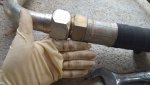
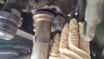
Since the tanks go in so many different places, this means all the hoses and pipes are different and specific to your application. These can be very expensive.
The second issue is A2 versus M939/M939A1. The PTO, shift tower, PTO shift cable, PTO shift cable mounting bracket (bolts to the front of the PTO), PTO driveshaft are all A2 specific. The easiest way to identify the A2 PTO is that the upper center bolt is accessed from inside the PTO. The earlier model is an external bolt. The shift tower is A2 specific because of the different doghouse/firewall on an A2. The A2 tower is the one furthest away from the camera in the 2 shots below.
View attachment 657287View attachment 657288
The shifters themselves I believe to be the same from M939/M939A1 to M939A2 and I used the early shifters in our A2 tower, but the TM drawing is confusing here, because in the A2 schematic, they definitely look different. However, they're "greyed" out and the subsequent parts list doesn't even give a part # for them, so I had to assume they were the same as the pre-A2 shifters. See the difference:
View attachment 657303View attachment 657304
While I am discussing this, there are quite a few issues with the TM's regarding this job. A lack of proper identification is chief amongst them. There are multiple schematics that don't say what model they're for. For instance.....................................
Here, the schematics for the dump and the wrecker are clearly labeled underneath:
View attachment 657301View attachment 657300
And the only other schematic that covers the linear valve and pump just generically says "Front winch pump, linear valve and related hoses"............ So which models does this work for? It's up to you to guess and find out!
View attachment 657302
Anyway, the point of all of the above is you need to be an educated consumer. Make sure you know what you're buying and what you need.
Alright, on to the install-that's where the real misery is.
So, on any job, always do the most miserable part first. Since everyone knows M939 tranny PTOs are a nightmare, that's where I started.
Some folks say they just kept wiggling it until it fell into place. Their wiggle skills must far outweigh mine. The issue here is that the PTO is too close to the frame. They should have moved the powerpack over an inch or so or made a smaller PTO because the only way I was able to get the PTO installed was removing the left and right rear motormoounts, the right front motor mount bolt, the upper mount to radiator brace, the lower left front engine to radiator brace and the transmission mount (above the tailshaft). You do all this so you can pull the entire powerpack (engine/trans) over to the drivers side. I put a strap around the transmission tailshaft and ran a ratchet strap out above the framerail to a tree. I had to put a fair amount of arm into it to get it to move over far enough.
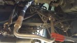
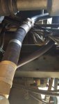
Below, you can see where we're going.
View attachment 657308View attachment 657307View attachment 657309
Get your strap on.
View attachment 657310View attachment 657311
Removed motor mounts
View attachment 657312View attachment 657313View attachment 657314View attachment 657315
More in the next post. It'll take a few minutes, be patient.