• Steel Soldiers now has a few new forums, read more about it at: New Munitions Forums!

  • Microsoft MSN, Live, Hotmail, Outlook email users may not be receiving emails. We are working to resolve this issue. Please add support@steelsoldiers.com to your trusted contacts.


MEP-002 pump problem

Offgrid12

Member
30
41
18
Location
NY Adirondacks
Hello,

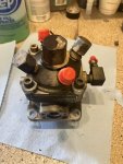
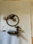
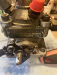
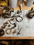
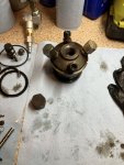
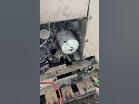
I am having a problem with the injector pump on my MEP-002.. I use this generator off grid so I use it a quite a bit. I bought it with about 500 hrs and I am up to about 3000 hrs now.

The problem I am having is the injector pump isn't regulating the RPM's correctly.. Let me try to describe this problem. When you put a load on the generator, the governor pulls the throttle linkage on the IP to handle the load. When you disconnect the load, the governor brings the throttle back down to where it was.. However, the RPM's do not come down when the throttle linkage goes down.

I can get the RPM's back down by pushing the throttle down pretty far by hand.. So something seems wrong with the injector pump... Was wondering what you guys thought about this problem? Thanks!
 

Ray70

Well-known member
2,378
5,094
113
Location
West greenwich/RI
With the gen running under no load, at 60hz, 1800 RPM, the slightest finger touch on the linkage should result in a big change in RPM.
If you move the linkage and aren't getting much of a change, or the linkage feels sticky etc. there is probably something sticking or broken inside the IP.
I've rebuilt a lot of these pumps and one time I had a similar case and the cause was that the tip of the throttle lever pin ( #16 Plunger sleeve pin ) had broken off where it engages the Plunger sleeve itself ( #8 ) )

Other than the rpm control issue, does the machine still perform correctly? Hold a load etc?


plunger pin.JPGSleeve.JPG
 

Offgrid12

Member
30
41
18
Location
NY Adirondacks
Other than the rpm control issue, does the machine still perform correctly? Hold a load etc?
It does seem to run well and handle a load... I started to notice the problem when I was about to shut down the generator. I would flip the breaker off which would take the load off the genset. The governor would then quickly decrease the throttle with the load gone, but RPM's were not coming down. (The Hertz meter would be pegged on 65) I did check it with a separate meter as well.

The governor is working perfectly... If I touch the linkage and move it one way or another, the governor brings it right back. Its just that the RPM's are not corresponding to throttle position. Maybe I will disconnect the governor linkage like you say and see how the throttle shaft (14) feels. Thank you for your help
 
Last edited:

Ray70

Well-known member
2,378
5,094
113
Location
West greenwich/RI
While you're in there, make sure the spring loaded linkage arm ( with the ball and socket ends ) connecting the IP to the governor arm is ok.
The linkage should pull itself together ( shorten ) and be able to stretch apart ( lengthen ) only when the stop solenoid pushes down on the IP throttle control arm, and check to make sure the lower ball socket that snaps onto the ball stud sticking out of the IP throttle control arm hasn't cracked or broken.
 

Offgrid12

Member
30
41
18
Location
NY Adirondacks
Well getting back to this thread..

I got around to pulling the IP. Also removed the throttle shaft. The pin on the end that Ray mentioned looks to be intact. So looks like I’ll have to dig deeper. I did see the thread here about a complete tear down. I’m not knowledgeable at tearing down pumps, but we’ll give it a try.
 

Attachments

Ray70

Well-known member
2,378
5,094
113
Location
West greenwich/RI
When you reassembled the pump I assume you got the flat of the throttle lever pin to engage into the slot in the plunger sleeve?
Sometimes it can be difficult, but 99% of the time the throttle control unit won't seat all the way unless the pin is engaged or the plunger sleeve is completely out of position.
 

Offgrid12

Member
30
41
18
Location
NY Adirondacks
Well I haven’t taken it apart yet.. just took out the throttle shaft to check that small pin on the end.
I’m hoping I find something wrong it to explain the problem I was having. I’ll update when I get farther into it.
 

Offgrid12

Member
30
41
18
Location
NY Adirondacks
Got it taken apart, everything came apart easily. Only problem is everything looks good. I was hoping to see a something to validate the problem I was having.

I'm thinking of getting a gasket/seal kit if its still available, and putting it back together. The only thing I noticed was there did not seem to be a gasket under the delivery valve cap (#16 above). Not sure if that makes any difference.

Not sure what the problem could be at this point. I would appreciate any suggestions. Thanks!
 

Attachments

Last edited:

Ray70

Well-known member
2,378
5,094
113
Location
West greenwich/RI
Regarding the seal under the delivery valve assy. it is pretty common to find it either deteriorated or missing, it's just a paper thin piece of plastic that helps hold the assembly in place during assembly. It will cost you $30+ to get a new one, but assembling vertically on a bench you don't need it at all!
When assembling horizontally on a gen, a dab of grease helps hold it in place if you have trouble.

As far as the erratic RPM, I do not know. I have a log splitter that I built out of an 002 and it tends to do something similar at times. RPM's creep up when not under any load and come back down when I start using the hydraulics for a few seconds. I had rebuilt the injectors, IP and everything but never figured it out, been just living with it. At some point I would like to fix it and will pass along anything I happen to find. I'm a little curious if IP timing could be off possibly.
 

Offgrid12

Member
30
41
18
Location
NY Adirondacks
Thanks, I'm thinking ill just get the rebuild kit and put it back together. I guess its possible that the erratic RPM's could be a different problem, but sure seemed to be an IP problem.

It has always been a good runner. It starts up good, and runs with no smoke at all. Before I pulled the IP, I put the flywheel pointer on the "PC" mark and then stuck an 1/8 drill bit in the side of the IP to see if I found the timing slot, and I did. There where no shims under the IP.
 

Ray70

Well-known member
2,378
5,094
113
Location
West greenwich/RI
Strange that there wasn't a shim under there. Never seen one without a shim.
For pump timing I meant the timing button under the cap where the pump rides on the cam.
I would suggest rebuilding the pump, install it per the TM instructions and perform the "pump flow" IP timing procedure to see if your timing button thickness is correct. I would assume things would be OK since this machine previously ran good, however the absence of a shim seems to indicate someone has removed the pump in the past and may have changed the pump which would typically require a different timing button.
The shim under the pump sets the backlash between the pump and cam gear, so you may want to check into that as well.
If needed, I have several new shims in my parts stash.
 

Offgrid12

Member
30
41
18
Location
NY Adirondacks
I got the gasket kit, and I am getting it back together..

I had one quick question, on the #5 spacer I wanted to make sure I put that in correctly. When I removed that VALVE ASSY. #4, there was a black spacer on it. I removed the black one, and slid the new orange one on from the kit on. Then put the valve assy in the head. It seemed correct, its just when I read the thread in the sticky section about the pump rebuild, it said that the orange spacer goes in the hyd head first.

This is paragraph i'm talking about from the other thread--

"I notice now that I didn't get pics of the delivery valve assembly back together. When the housing is empty, the little spacer goes in first (sits in a little groove you'll see once it's apart).. then the valve (and needle valve). Then the spring and then the holder. After the holder is torqued, the cap can be re-installed."

edit - Is this what your talking about in post #10 Ray70?

Sure appreciate the help.

Sleeve.JPG
 
Last edited:

Ray70

Well-known member
2,378
5,094
113
Location
West greenwich/RI
In post #10 I'm talking about #5, which is the orange paper thin plastic ring you just installed.
BTW, you installed it correctly, that's the way I have always done it. Slide it onto the body of the delivery valve assembly (#4 )
Then stick it into the main body.
 

Offgrid12

Member
30
41
18
Location
NY Adirondacks
Got the pump back on and everything buttoned up. Started up good after some cranking. Unfortunately, the pump rebuild didn't solve my original problem. The RPM's are still creeping up on their own. Can't get it to maintain a steady RPM. It still seems like an injection pump problem, but that pump seemed to be in real nice shape.

I found that the bolts on the intake to cylinder has loosened up. I thought that my be causing issues, but I tightened those up, with no change.

I put the kilowatt meter on it to watch the hertz, and at 60hz, I had 155V! Now I am thinking that this issue with it not maintaining correct RPM may have messed up the voltage regulator?
 

Ray70

Well-known member
2,378
5,094
113
Location
West greenwich/RI
That is possible, if the volt meter is up around 300+ volts ( when in 120/240 mode ) and you can't adjust it down with the panel knob, that's a sure sign that you smoked 1 or more of the 3 transistors on the VR.
If so, you can replace the transistors, or KKlopp makes a super nice, modern, drop in replacement.
 

Chainbreaker

Well-known member
1,749
1,838
113
Location
Oregon
Since you have ~3000 hrs on the Hobbs and due to effects of MEP-002a's long term vibration on components & wiring you should open the Control Panel (loosen the Zeuss Fastners at top of panel & it swings down (with engine off & battery disconnected of course) and closely inspect inside looking for loose terminal connections, broken or chaffing wires.

Put a screwdriver to all the screws to make sure they are snug in all the Terminal Block screws where connections are made and verify no loose, frayed, or shorted wires in the harness in the control box.

A few years back I had one of my gensets suddenly go high on voltage output while I had it powering my house during a power outage. As I recall the voltage was similar to the range you are reporting. I took a chance & replaced the Voltage Regulator Board with one of "Triple Jim's" redesigned boards.

However, in my situation... after replacing the Voltage Regulator Board with one of Triple Jim's boards back then... I still had the Voltage High Output issue similar to what you are reading. My issue turned out to be that vibration had broken a "Transformer winding lead" coming out of the "T1 or T2 transformer" going to one of the transformer's screw tabs mounted on the transformer up towards the top left side of the control box. So, the wire attaching to it from the wiring harness had no continuity to the Transformer, it was a N/C causing voltage to shoot high.

Regardless, I'm glad I replaced the VR board as it has much better components, especially the output transistors, than those used back in the 70-80's timeframe when those electronics were designed & fabricated. (BTW, I believe KKlopp said he bought the rights from Jim to reproduce it and may have also made some further circuit/component improvements. From what I saw of it in a photo it appears to use very nicely fabbed board with top-notch components!

Regardless of what you find, it's worthwhile to consider buying a new more robust designed VR board & install it and keep the original board as a spare should it prove to still be electrically functional.
 
Top
AdBlock Detected

We get it, advertisements are annoying!

Sure, ad-blocking software does a great job at blocking ads, but it also blocks useful features of our website like our supporting vendors. Their ads help keep Steel Soldiers going. Please consider disabling your ad blockers for the site. Thanks!

I've Disabled AdBlock
No Thanks