• Steel Soldiers now has a few new forums, read more about it at: New Munitions Forums!

  • Microsoft MSN, Live, Hotmail, Outlook email users may not be receiving emails. We are working to resolve this issue. Please add support@steelsoldiers.com to your trusted contacts.

MEP-002 pump problem

Chainbreaker

Well-known member
1,749
1,841
113
Location
Oregon
In reviewing your video, it sounds like your engine is racing well above 1800 RPM. I'm wondering if perhaps there might be an issue with the Governor function operation.

Just to cover all the bases... have you taken a look at the "Governor Arm Assembly" mechanism? With engine off, raise the Close To Run Cover shroud and inspect the governor arm & all linkages. Ck to make sure nothing is bent or missing as compared to the diagram in the -24P manual (see below)

How does that linkage look as compared to the illustrations on printed pg. #132 of the -24P parts manual?

The HOOK END of the Governor Spring should be about midway down on the threaded section of the Governor Arm with the adjusting star thingy up above it . IIRC the hook on spring end typically sits in about the 4th groove or halfway.
 

Offgrid12

Member
30
41
18
Location
NY Adirondacks
Looking at that vidio, your Hertz should come RIGHT up. No wait, no hesitation. And its not. Have someone else start the set, and you film the K5 when it moves the IP arm to full fuel.
Ok, Ill get a video of that soon.

In reviewing your video, it sounds like your engine is racing well above 1800 RPM. I'm wondering if perhaps there might be an issue with the Governor function operation.

Just to cover all the bases... have you taken a look at the "Governor Arm Assembly" mechanism? With engine off, raise the Close To Run Cover shroud and inspect the governor arm & all linkages. Ck to make sure nothing is bent or missing as compared to the diagram in the -24P manual (see below)

How does that linkage look as compared to the illustrations on printed pg. #132 of the -24P parts manual?

The HOOK END of the Governor Spring should be about midway down on the threaded section of the Governor Arm with the adjusting star thingy up above it . IIRC the hook on spring end typically sits in about the 4th groove or halfway.

I will double check, but from what I could tell the governor in functioning correctly. Yes, the RPMs will slowly creep up pretty high. You can see on the hertz meter that it will keep going up to about 90Hz. When the RPM's start racing like in the video, it appears the throttle position is not changing. That's what had me puzzled.
 

Ray70

Well-known member
2,390
5,158
113
Location
West greenwich/RI
Looking at that vidio, your Hertz should come RIGHT up. No wait, no hesitation. And its not. Have someone else start the set, and you film the K5 when it moves the IP arm to full fuel.

I agree 100% with Guy, looking at the video there is something definitely wrong. The machine starts out slow, a little low on RPM's and builds from there.
It should come right up to 60Hz ( or whatever the throttle is set at immediately.
I'm wondering if it's running on both cylinders or just one?

The video Guy suggests may help shed some light on things. Upon initial start the throttle linkage should go wide open as soon as you attempt to crank.
Once the machine fires up it will go to W.O.T and the governor linkage should immediately start acting and regulate the RPM's at the set speed.

Also get a shot of where the governor spring is on the adjustment screw. as CB mentioned it should be around 3-4 winds up from the bottom, no more.

The engine seems to be going to W.O.T slowly and the governor is not regulating the RPM's
If you manually lower the throttle setting, what happens? Can you bring the RPM down or does it just continue to climb to 90hz?

You may have already covered this, but are you sure the governor linkage isn't rubbing on the hole where it passes through the sheet metal?
 

Offgrid12

Member
30
41
18
Location
NY Adirondacks
Here is a video I snapped of the throttle when starting.. you can see the HZ meter in the video as well. Sorry it was a little shaky for a little bit until I held the camera steady.

It looks to me like -

- Throttle position is NOT changing when engine is rapidly revving.

- Governor linkage is adjusted properly, and not rubbing (Exactly how Ray70 describes it above.)

- I loosened an injector nut on each line when running to make sure both cylinders were firing (they were) I didn’t video this.

Let me know if you guys see anything in this video.. Thank you


Last edited:

Guyfang

Moderator
Staff member
Moderator
15,960
22,324
113
Location
Burgkunstadt, Germany
Understand, when this set starts, it goes to FULL fuel position. When it hits 60 hertz, (1800 RPM) the gov. takes control and stops the engine from going faster.

This is what I saw, and what I THINK I saw.

The engine started. The solenoid went to full fuel. Its is already going faster the 1800 RPM, a few seconds after starting. And the RPM keeps going higher. That is maybe why everything vibrates so badly. And it never levels off. The linkage never comes out of the full fuel position.

So, I will ask you, have you screwed the manual hertz knob out too far?
You say the linkage is adjusted correctly. Did you do it IAW the TM?
The solenoid has no real control over the Hertz, other than FULL POWER. Have you tried to adjust the Manual control knob in, to slow the engine speed down?
 

Chainbreaker

Well-known member
1,749
1,841
113
Location
Oregon
Also, with engine off, can you temporarily raise & open the "Close to Run cover" & take a detailed still photo or video showing of the Governor Linkage Assembly? Take a shot looking from left-to-right (top of Rod assembly coming up from IJ Pump over to the attached spring as it attaches to the Governor Lever. Then with "Close to Run" cover still up & open, start it up from a cold start and video the Governor Linkage in action while it is running. That may be helpful to see what it is doing (if it binds up or anything appears misadjusted as it revs up.

FYI...on my -002's the Throttle Control black plastic knob on 2 different Gensets has ~ 1" to 1-1/2" of the aluminum rod shaft showing from back of Black Plastic Control knob to the frame mounted aluminum sleeve rod retainer face). That usually starts me out at ~61.5 Hz unloaded.
 

Ray70

Well-known member
2,390
5,158
113
Location
West greenwich/RI
To me it looks like the governor attempts to lower the engine speed just after startup ( right when the linkage goes from full up to about 1 1/2" space between the solenoid and the linkage.
The governor for some reason seems to have no effect on engine speed.
Can you manually lower the RPM with the throttle knob at all? Or do you get the same effect regardless of where the throttle knob is.
I assume you checked to see that the cable is still properly attached to the linkage under the blower wheel shroud?
Can you get a picture of the throttle linkage and governor linkage as well as the spring?
While running, what happens if you manually push down on the IP lever right where it comes out of the pump?
 

Offgrid12

Member
30
41
18
Location
NY Adirondacks
To me it looks like the governor attempts to lower the engine speed just after startup ( right when the linkage goes from full up to about 1 1/2" space between the solenoid and the linkage.
The governor for some reason seems to have no effect on engine speed.
Can you manually lower the RPM with the throttle knob at all? Or do you get the same effect regardless of where the throttle knob is.
I assume you checked to see that the cable is still properly attached to the linkage under the blower wheel shroud?
Can you get a picture of the throttle linkage and governor linkage as well as the spring?
While running, what happens if you manually push down on the IP lever right where it comes out of the pump?

To me it looks like the governor is working properly... What I am seeing is the RPM's all over the place, even with the throttle arm being held in the same position by the governor. This is what has made me think that the injector pump has some kind of issue.

So in that video, and all the testing I have been doing, the speed adjustment knob has been pushed all the way in. So all I can do is raise the speed.
I did check that the cable is connected under the blower shroud is connected, which it is..

I have played with the throttle while its running by pushing the throttle arm down with my finger. So when its revved up high like in video, I can press the throttle arm down and bring it down to the mid 50hz range. When I take my finger off, the governor arm immediately brings the throttle arm back to where it was. BUT, the RPMs sloooowly come back up. Not fast like it should.

I can take some more pics of the governor setup. This is the only Mep002 I've had, but I've had a hand full of Onan civilian generators, so I am used to adjusting the governors for droop, etc..
 

Ray70

Well-known member
2,390
5,158
113
Location
West greenwich/RI
When you take pics of the governor and throttle cable, also get a picture of the arm that the cable attaches to relative to the bracket it's mounted to.
That arm should be essentially 90* straight out , perpendicular to the centerline of the engine block.
Also try to get a picture of where the linkage coming up from the IP attaches to the governor arm. there is a slot in the end of the governor arm, the IP linkage should be almost all the way out at the far end of the slot and the nuts should be just about even with the top surface of the fuel solenoid.
Out of curiosity, prior to this RPM issue, where was the throttle knob at when running at 60Hz? Was it pulled out fairly far, close to fully closed? I assume it was working correctly prior to this issue popping up?
 

Offgrid12

Member
30
41
18
Location
NY Adirondacks
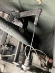
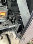
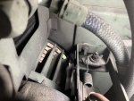
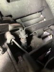
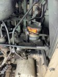
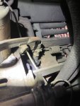
Here are some pics of the governor setup.

Yes, before the problem started the throttle control knob was always pulled out somewhat to get about 61hz no load..
I can’t remember exactly how far out. I ran it for over 2000hrs with minimal to no adjustments to the speed.

IMG_1144.jpegIMG_1143.jpegIMG_1142.jpegIMG_1141.jpegIMG_1140.jpegIMG_1137.jpeg
 
Last edited:

Chainbreaker

Well-known member
1,749
1,841
113
Location
Oregon
In reviewing the photos, I don't see anything that jumps out as being off.

A close-up video with Cover Open from "starting to running" might now tell us if the Governor mechanism is acting on the IJ Pump or not. The fly ball mechanism is reported to be darn near bullet proof, but you never know... things can break.

If Governor & linkages are in fact adjusted & working properly that might mean that something in IJ pump is broken/misassembled or loose...
 
Last edited:

Chainbreaker

Well-known member
1,749
1,841
113
Location
Oregon
Also, if you have someone that can help you video or work the throttle adjuster knob, it might be informative.

After it starts have someone push in on the throttle control adjuster below instrument panel and then work it back out (Slow RPM then Fast RPM) while filming the Governor Assembly with "Close to Run" cover open. Maybe do that 2-3 times so we can see movement in all the linkages and hear the engine responses.

That way, we might be able to determine what effects the "throttle control adjustments to governor mechanism" & its associated linkages have on the IJ Pump mechanism & expected RPM's while running...or if it doesn't have any effect at all.

Though, I wouldn't spend a lot of time running it if it goes to high rpm's & stays there no matter the throttle control knob movements.
 

Offgrid12

Member
30
41
18
Location
NY Adirondacks
I'll try and shoot another video soon.
If I had a spare injection pump around I would probably put it on to see if that fixes it, but I do not.
It looks to me like the IP is not regulating the engine speed like it should.
 

Ray70

Well-known member
2,390
5,158
113
Location
West greenwich/RI
So the biggest "problem" I see is that the lever that the throttle cable and governor spring attach to are definitely all the way back in the "Idle" position, therefore the engine should currently be running at minimum RPM, ( less than 55 Hz. ) not wide open throttle like it is.
Since this machine was working good for 2000+ hours, something must have broken somewhere.
Being it was running good before eliminates things like timing buttons and such.
I think you could be right that there is still an issue either internal to the IP or with the governor.
There are some known issues with the pin falling out of the governor arm inside the timing gear cover, which eventually will cause catastrophic damage if it falls into the timing gears.
I'm curious if that pin has come partially out or if there is another problem with the Governor flyweight assembly?
Unfortunately checking the governor requires quite a bit of disassembly to get into the timing cover.
 

Chainbreaker

Well-known member
1,749
1,841
113
Location
Oregon
I believe Ray is referring to the parts identified on Printed Pg's 168-170 of the -24P Parts Manual. There is a Yoke assembly there, that works the governor shaft, plus the flyball A'ssy shown on those pages. I think the pin he is referring to is item #10 (Spring Pin) but not 100% sure.
 

Ray70

Well-known member
2,390
5,158
113
Location
West greenwich/RI
C.B is correct. That's what I'm talking about. The other thing that bothers me is the bouncing up and down of the throttle lever / Governor arm as well as the fact that the governor arm is not attempting to lower the throttle arm despite the RPM's climbing higher and higher.
The higher the RPM's climb, the further the governor should be attempting to close down the throttle.
 

Chainbreaker

Well-known member
1,749
1,841
113
Location
Oregon
@Ray70 So... if Offgrid were to find that Pin (Item #10 as noted in post #35 above) as the issue, or even if it weren't the issue & it was taken apart what is the fix to ensure that it doesn't ever come loose & wreak havoc in the engine internals?

If that pin were found detached, I would think one would "not want to reuse it" and purchase a new pin (roll pin or what?). Would you clean out the retention hole with solvent & apply something like JB Weld into the retention hole to hopefully ensure it never came out again? Or be more aggressive & Tack weld it... Or?

The fix would seem to apply to anyone, MEP-002a or MEP-003a owners, who are taking that cover off for any reason as a "preventative fix".
 

Offgrid12

Member
30
41
18
Location
NY Adirondacks
Thanks for the tips guys, I appreciate it.

There is a fair amount of bouncing up and down on the throttle shaft when running like you said, wasn't sure if that was normal or not. Oscillation I guess you might call it. But the governor seems to hold the throttle in about the same position more or less. As Ray said though, it does not attempt to compensate for the RPMs climbing.

The hardest part about checking to see if that pin was falling out seems to be taking off the blower wheel off the crank? Maybe ill tackle that one of these days. I do see the Pin in the diagram, but I can't picture exactly see what its function is.

I was going to mention I did end up seeing the shims behind the injection pump when putting it back together. They were just so seized to the block which made me think there were no shims at first.
 
Last edited:

Ray70

Well-known member
2,390
5,158
113
Location
West greenwich/RI
Search around here more, there was recently a post where a member had catastrophic engine failure due to that pin coming out and falling into the timing gears. I believe he ended up repairing things and threaded the hole in his replacement cover and made a new pin that was threaded on the end.
Loctite retaining compound or possible even epoxy might be better than nothing.
As for the blower wheel, I made a very simple puller using a small block of 1/2" thick steel, tapped the center for a 1/2" fine thread bolt and drilled 2 thru holes for 2) 5/16"-18 grade 8 bolts.
You can also use a steering wheel puller. You want to use the 2 threaded holes in the hub, don't bother trying to fight with something like a 3 jaw puller.
Run a tap through the holes before you screw in your 5/16" bolts as the threads are often either rusty or filled with dirt.
 
Top