• Steel Soldiers now has a few new forums, read more about it at: New Munitions Forums!

  • Microsoft MSN, Live, Hotmail, Outlook email users may not be receiving emails. We are working to resolve this issue. Please add support@steelsoldiers.com to your trusted contacts.


MEP 005A No output

flyanbrian

New member
11
0
0
Location
South Florida
Hello all,

I am new to this websiteand I wanted to say it has been a wealth of info so far. I recently purchased an MEP 005A. After cutting off the lunette ring (coudn't get it out) I welded a piece of 3" square tubing under it and installed a titan hydraulic brake actuator. Works great, tows great, stops great! I installed new fuel filters and swapped over to a spin on oil filter. When I tried to start it, it would start and run for about 30 seconds then die. You guys really understated the importance of the little glass check valve! Once I drove it out and cleaned it up the genset started and ran great! After flashing the field the output came upnto 240 volts. Forgot to mention I did the single phase conversion too. I walked around it and checked for leaks but when I got back to the control panel the output was zero. Now when I flash the field the output comes up but goes away when I let go of the switch. I am about to pull the manuals and get into it but I was hoping somebody would kow the problem right off hand.

Anyway, thanks for all the good info.
 

flyanbrian

New member
11
0
0
Location
South Florida
OK, here is an update. I found transformer T2 in the static exciter (regulator?) assembly A11 had blown forth its guts! I see that the power for this transformer is directly from the voltage connection board Terminals T8 and T9. As I said before, I did the single phase conversion per the YouTube video (although my board was a little different, the neutral copper bar was on the underside of the board, but the terminals and wires all seemed to agree). I went back into this to see if I got something wrong but it all looks OK except the gen wire to T12 was loose. I am going on the assumption that the exciter requires 120 Vac from the output of the generator. When I look at where the wires are connected (T8 and T9) this appears correct. The output of the genset was correct when I first started the unit, and even now when I use field flash. Has anyone else had this issue? Does anyone have a drawing for the internals of A11 or specs for the transformer? Where can I get a new A11 assembly or transformer?
 
Last edited:

sewerzuk

Member
524
9
18
Location
Seaside, OR
I may have an extra one on my shelf; I will check this weekend. But...you would probably be better off just replacing the transformer...should be reasonably easy to find a suitable replacement for under $20.

I haven't done exhaustive testing on the single phase mod, but I have done extensive testing with it. There is no way for me to foresee all of the potential pitfalls associated with the different generators out there (who knows what field changes, different versions, etc. are out there). But, I do know that at least a few dozen people have completed the modification successfully and have no problems. I worked my "test" -004a REALLY hard after the single phase mod, including some very unbalanced loading, extended overloads, and short circuits. It handled all of that with no problem. So...I do believe that, provided you did the swap correctly, the single phase mod was not the source of the burned up transformer.

Did you load the set at all while it was still configured for 3 phase?
Did you happen to check the load meters on the set once you got it running in single phase? One person mis-wired one of the 12 leads on his, and got a 60% load reading just because of the current through one winding...wondering if something similar might have happened on yours?
 

flyanbrian

New member
11
0
0
Location
South Florida
I don't think it is the mod. When I run the gen and hold the switch for field flash the voltage to the transformer is a nominal 120 vac. I hope it was just its time to go. Would you have the specs for the transformer? What is the output voltage and volt-amp rating?
 

sewerzuk

Member
524
9
18
Location
Seaside, OR
I don't think it is the mod. When I run the gen and hold the switch for field flash the voltage to the transformer is a nominal 120 vac. I hope it was just its time to go. Would you have the specs for the transformer? What is the output voltage and volt-amp rating?
I can probably find out; but I'm away from my shop right now...I'll try to get some info for you this weekend.
 

flyanbrian

New member
11
0
0
Location
South Florida
OK, another update. Turns out the single phase mod was the issue. When the buss bar from terminals 10, 11, 12, and 13 is cut and rerouted the supply voltage to the transformer is reduced from 208 vac to 120 vac. This is what kills the transformer. In order for the mod to work in my case I needed to move wire X9J from T9 to T7. This should keep 208 vac to the regulator transformer T2. It is too late for me so I intend to replace T2 with a 120 volt primary model once I figure out the secondary requirements. The manual is not very accurate or complete making the job more difficult. Anybody out there with transformer specs would be a big help.
 

sewerzuk

Member
524
9
18
Location
Seaside, OR
I took a quick look at the schematic and can't figure out why that change would have caused the excessive current flow that damaged your transformer. I will need to spend a few minutes thinking things over! I know for sure that quite a number of people have completed the conversion exactly as I outlined it in my video and they have had no problems. I suspect even more have done the conversion who have not contacted me...you would be the first person who has experienced problems related to the swap (not due to a mis-placed lead). But, if that was indeed the cause of the transformer burning up, then I certainly need to know! If I can come up with a reason why this may have been the culprit then I will need to edit my conversion video.

I did not have time to check for a spare A11 assembly...we had a pretty massive forest fire that I was actively engaged in fighting over the weekend that took up all of my spare time. I will attempt to check through my spare parts in the next few days to get you the transformer specs.
 
Last edited:

flyanbrian

New member
11
0
0
Location
South Florida
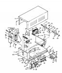
I am using the TM5-6115-465-34 manual and the figure (TM5-6115-465-34/5-30(1))does not look exactly the same as the one you used. With that being said the burned up transformer in the attached figure is item 29. In the schematic it would be T2. Per the wiring diagram it was originally wired (Via J13 Pins L & M) to the gen output terminals across (effectively) L2-L3 (Terms T8 & T9). My assumption is that with this being an active circuit, and with supply being low due to the revised configuration, the regulator overstressed the transformer since this is the current supply for the field. I also noted that the voltage regulation circuit utilizes a crude crowbar configuration in Q4 such that when voltage is too high, Q4 is allowed to oscillate, which in turn gates on the SCRs, sinking the source to ground (efectively shorting the transformer). This all implies that T2 is a very lossy transformer and might be hard to replace with a generic model. I am thinking of replacing the entire AVR with a universal model, but I need to know what the gen field current requirement is. I am also still trying to figure out the field flashing connections, these drawings are horrible! I am going to assume that an AVR with 6 amp capability will suffice unless you have more information.
 

sewerzuk

Member
524
9
18
Location
Seaside, OR
Well, it certainly sounds like you know your electronics. I am a little hobbled here, as I currently have no -004's or -005's to actually look at.

Keep in mind that L2-L3 is designed to have different voltage outputs (via the voltage reconnection board) from the factory. When in 120/208 mode, that would be 120v; in 240/416 mode it would be 240v.
edit: nevermind; I see that, when configured for 3 phase wye there would always be 240v between T8-T9

I will see if I can dig up the specs, or an exact replacement, for that transformer...

The best schematic for the DC side of the set is on page 345 of the 9-6115-464-12 TM. The flashing circuit simply applies battery voltage to the field when the master switch is in start, limiting current via resistor R35.

The next time I get an -004/-005 in my shop with the single phase mod, I will measure primary and secondary current on that transformer to see if the single phase mod affects it.
 
Last edited:

flyanbrian

New member
11
0
0
Location
South Florida
Actually, if you look closely at the voltage reconnection board you will see that T8 and T9 will always be 208 volts, in either configuration. This is actually a good design! I'm surprised!
 

sewerzuk

Member
524
9
18
Location
Seaside, OR
Actually, if you look closely at the voltage reconnection board you will see that T8 and T9 will always be 208 volts, in either configuration. This is actually a good design! I'm surprised!
:)

Beat you to it.
I realized that and edited my post mere seconds before you replied! Trying to locate a suitable replacement, but I do have some data on that transformer:

AARGReliability IndicatorNot established
ABKQCenter to Center Distance Between Mounting Facilities Parallel to Length4.320 inches minimum single mounting facility single center group and 4.440 inches maximum single mounting facility single center group
ABKRCenter to Center Distance Between Mounting Facilities Parallel to Width3.690 inches minimum single mounting facility single center group and 3.810 inches maximum single mounting facility single center group
ABTDMounting Slot Width0.312 inches nominal single group
ACZBFrequency Rating50.0 hertz nominal single component or 60.0 hertz nominal single component
ACZCInput-Output Phase RelationshipSingle phase to single phase single component
ACZXWinding Shielding MethodInternal shield brought out to terminal single component
ADAQBody Length5.190 inches minimum and 5.310 inches maximum
ADATBody Width5.000 inches maximum
ADAUBody Height4.688 inches minimum and 4.812 inches maximum
AGAVEnd Item IdentificationWsd: generator set, 30 kw, 60 hz, skid-mounted (3ID) (MEP-005A); generator, 15 kw, diesel, military standard family; maint facility, night sight (nsmf), tam E10227; aircrafts, stratofortress B-52 and B-1B
AKNAInclosure TypeFully inclosed
AKPVMounting Facility Quantity4 single group
AXGYMounting MethodFlange single group and slot single group
BPLCWinding Function and Quantity1 primary single component and 1 secondary single component
CRTLCriticality Code JustificationFEAT
CWJSWinding Operating Voltage208.00 ac volts nominal single component single primary
CWJSWinding Operating Voltage124.00 ac volts nominal single component single secondary
FEATSpecial FeaturesWeapon system essential
TTQYTerminal Type and Quantity5 tab, solder lug and 1 wire lead W/lug
 
Last edited:

flyanbrian

New member
11
0
0
Location
South Florida
Ok, here is another update. I bought a replacement regulator from Delk's Surplus in Asheville, NC. I moved the wires on the voltage reconnection board and verified that 208 volts are going to the regulator, fired it up and it works great! Had to send the old one back to them so I won't be able to experiment with it but I am happy. All those who have done the single phase conversion need to make sure that the voltage to the regulator is correct and I am sure these things will carry more than rated load.

Thanks to all those who helped.
 

1800 Diesel

Member
768
25
18
Location
Santa Rosa County, FL
Ok, here is another update. I bought a replacement regulator from Delk's Surplus in Asheville, NC. I moved the wires on the voltage reconnection board and verified that 208 volts are going to the regulator, fired it up and it works great! Had to send the old one back to them so I won't be able to experiment with it but I am happy. All those who have done the single phase conversion need to make sure that the voltage to the regulator is correct and I am sure these things will carry more than rated load.

Thanks to all those who helped.
For us electrically challenged folks, can you please elaborate on what terminal voltages I need to check? I've done two single phase mods (MEP4 models) so far and have a few more waiting their turn....
 

1800 Diesel

Member
768
25
18
Location
Santa Rosa County, FL
I have 006a that does the same thing going to swap some parts this weekend since i have 6 of them will post up what i find .
Good morning all--just wondering how you ended up with the 6 MEP6 gensets....Obviously that size unit is about 4xs the KW needed for the average whole-house backup gen...are you working these for shops/businesses with larger 3-phase loads? Just curious, not being critical...
 

1800 Diesel

Member
768
25
18
Location
Santa Rosa County, FL
No i got these in a trade deal just getting them going and going to sell them 3 down 1 to go now 2 for parts
Sounds like a plan...I have a few MEP4s in work--getting them fit for duty with hurricane season upon us...much work to do & so little time....I might need a few parts for some I have--things that would be common to both the 4 & 5 models...
 
Top
AdBlock Detected

We get it, advertisements are annoying!

Sure, ad-blocking software does a great job at blocking ads, but it also blocks useful features of our website like our supporting vendors. Their ads help keep Steel Soldiers going. Please consider disabling your ad blockers for the site. Thanks!

I've Disabled AdBlock
No Thanks