• Steel Soldiers now has a few new forums, read more about it at: New Munitions Forums!

  • Microsoft MSN, Live, Hotmail, Outlook email users may not be receiving emails. We are working to resolve this issue. Please add support@steelsoldiers.com to your trusted contacts.


MEP-804B Problem Starting

Rik

Member
36
24
8
Location
California
I have a MEP-804B (Yanmar Engine) and I have a problem that just developed.

I was using the Generator and shut it off for a few minutes and then when I went to restart I get nothing, meaning the fuel pump does not run, the engine will not turn over and thus will not start.

History: Unit has 470 hrs on it and performs excellent. In the past when I turn the ignition switch to start it cranks over and starts or I hear a click, if I hear a click I simply turn the switch to off and repeat and for some reason the 3rd attempt (if it does this) is starts and on with life.

Trouble shooting:

I checked the batteries and they are putting out 25V
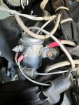
I can jump the starter and the motor spins over but does not fire up
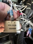
I checked the breaker behind the panel (7.5 amp) and it has 25V in and out
I checked the power to the ignition switch and it has 25V on terminal #8
I checked the voltage at the starter and it has 25V
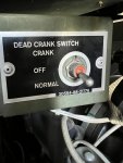
I went to the dead crank switch and it is in the run position but it will not crank over the motor when I flipped the switch to the crank position
I made sure that the emergency shut off was in the run position

So:

I thought it was the ignition switch so I purchased on from 'Green Mountain" and I just changed it and to my surprise the problem still exist.

What could cause the engine to not start, crank, turn on the fuel pump, open the fuel cutoff ??? Is there a breaker somewhere that I do not know of?

Thanks in advance.
 
Last edited:

Guyfang

Moderator
Staff member
Moderator
15,909
22,184
113
Location
Burgkunstadt, Germany
This should be an easy thing to solve. Look at this schematic. Trace the wires from the BT-1 and BT-2. Thats the batteries. The 24 VDC comes from the BT-1 and BT-2, to the MT4. Check at MT4 at pins 1&4. You should have 24 VDC. The 24 VDC then goes from MT4-1 to S10-2 Mesure at S10-2. What do you have? Then at S10-3. What do you have.
1681315357047.png
 

Rik

Member
36
24
8
Location
California
Thank you!

Where is the MT4 located on the generator?

Currently my batteries go to a plug that accepts an outside power cord with the + on one side of the plug and the - on the other side of the plug.

From there (memory) the positive goes to the starter and then smaller wires go to?
 

Rik

Member
36
24
8
Location
California
I take it, you do not know how to read a wire diagram or TM's.

WIthin reason. The manuals do not show where things are located only a simple diagram for most of the items.

I downloaded the TM on the generator and it uses a block flow chart to explain things but makes no references as to their actual size/location so some things become an adventure to find.

I can trace this out but it's easier when I have a general idea as to the are as the area behind the control panel is not labeled MT4 and such. But I will search. My generator is 90 miles from my home location so it's a drive to find something if I have to trouble shoot multiple things and get feedback each time.

Any idea as to the problem?

Thank you!
 

Guyfang

Moderator
Staff member
Moderator
15,909
22,184
113
Location
Burgkunstadt, Germany
WIthin reason. The manuals do not show where things are located (Thats what the -24P parts TM is for) only a simple diagram for most of the items.

I downloaded the TM on the generator and it uses a block flow chart to explain things but makes no references as to their actual size/location (All electric parts are labeled next to the item.) so some things become an adventure to find.

I can trace this out but it's easier when I have a general idea as to the are as the area behind the control panel is not labeled MT4 (Is located behind the control panel) and such. But I will search. My generator is 90 miles from my home location so it's a drive to find something if I have to trouble shoot multiple things and get feedback each time.

Any idea as to the problem? It sound to me like the S10 is in the wrong position or that S17 is non op, or that the canon plug going to the control cube is loose or has fallen off. You are getting no power to the control cube. The lights should work, at least. The first place to check is MT4, The batteries are charged? They read at least 24 volts?

Thank you!
 

Rik

Member
36
24
8
Location
California
Yes, firs thing I did was suspect the batteries and I put the Fluke Meter on them and they make 25V at various points on the geneartor. Panel switch included. AMP Meter and other locations

I didn't download the -24P parts TM as I didn't know it existed but was starting to think I need to search for an electrical diagram

Thank you
 

Guyfang

Moderator
Staff member
Moderator
15,909
22,184
113
Location
Burgkunstadt, Germany
Yes, firs thing I did was suspect the batteries and I put the Fluke Meter on them and they make 25V at various points on the geneartor. Panel switch included. (What panel switch. Thats one reason I always refer to the switch name. no confusion then) AMP Meter (What amp meter? I assume the DC meter, M4) and other locations

I didn't download the -24P parts TM as I didn't know it existed but was starting to think I need to search for an electrical diagram

Thank you
 

Rik

Member
36
24
8
Location
California
Yes, firs thing I did was suspect the batteries and I put the Fluke Meter on them and they make 25V at various points on the geneartor. Panel switch included. (What panel switch. Thats one reason I always refer to the switch name. no confusion then) AMP Meter (What amp meter? I assume the DC meter, M4) and other locations

I didn't download the -24P parts TM as I didn't know it existed but was starting to think I need to search for an electrical diagram

Thank you
Sorry, the ignition switch. It has 25V on the #8Lug. Voltage drops when I turn the ignition switch to start and then leg 3 has like a 6V power running through it and I believe lug7 does as well.

Yes the "Battery Charge Ammeter" has the 25V on it's legs.

What I didn't check was the voltage to the "Dead Crank Switch" as getting to the backside of it is not an easy task.
 

Rik

Member
36
24
8
Location
California
About to drive the 2 hrs to the generator and after reading your comments, I have concluded (maybe incorrectly) that the MT4 is the "Battery Charging ammeter Shunt" and that the S10 is the "Dead Crank Switch" . I plan on checking the current and possibly making a jumper wire if the switch is bad to test it.

I looked over the manuals and I cannot find a page with the wiring diagram that you posted and printing off what you posted is very small and distorted when printed. Any source for a better diagram?

Thanks!
 

Rik

Member
36
24
8
Location
California
Yes, firs thing I did was suspect the batteries and I put the Fluke Meter on them and they make 25V at various points on the geneartor. Panel switch included. (What panel switch. Thats one reason I always refer to the switch name. no confusion then) AMP Meter (What amp meter? I assume the DC meter, M4) and other locations

I didn't download the -24P parts TM as I didn't know it existed but was starting to think I need to search for an electrical diagram

Thank you
I cannot find the MT4. I see that it comes off the alternator and I see nothing like this in the engine compartment and nothing labeled inside the control panel box

I see a solenoid next to the dead crank switch and some type of white plastic thingy inside the voltage panel

I checked the voltage at the alternator and it has 25V on the main terminal

The dead crank when set to normal has 25v on #1 and #2 and 0 on 3

With the switch in off only #2 has 25v and with the switch turned to crank #2&3 have 5.7V

Panel light switch has 25v but when switched to on it drops to 0.8V on both wires

The battery charger CB and the DC Control Power CB both have 25V across both lugs

The cannon plugs are tight

Confused
 

Attachments

Rik

Member
36
24
8
Location
California
I cannot find the MT4. I see that it comes off the alternator and I see nothing like this in the engine compartment and nothing labeled inside the control panel box

I see a solenoid next to the dead crank switch and some type of white plastic thingy inside the voltage panel

I checked the voltage at the alternator and it has 25V on the main terminal

The dead crank when set to normal has 25v on #1 and #2 and 0 on 3

With the switch in off only #2 has 25v and with the switch turned to crank #2&3 have 5.7V

Panel light switch has 25v but when switched to on it drops to 0.8V on both wires

The battery charger CB and the DC Control Power CB both have 25V across both lugs

The cannon plugs are tight

Confused
More photos
 

Attachments

peapvp

Well-known member
Steel Soldiers Supporter
1,033
1,056
113
Location
Basehor, KS
Dead Crank S10 pinout as follows:
#2 Com always 24V when battery connected
#1 crank
#3 normal
when you have 24V on #1 crank K2 should close (24V on K2 X1) that’s on the starter
check voltage on starter solenoid K2 and L4
give starter a couple whacks with the hammer
 

Rik

Member
36
24
8
Location
California
Dead Crank S10 pinout as follows:
#2 Com always 24V when battery connected
#1 crank
#3 normal
when you have 24V on #1 crank K2 should close (24V on K2 X1) that’s on the starter
check voltage on starter solenoid K2 and L4
give starter a couple whacks with the hammer
starter has 25v and I can jump the starter and the engine cranks fine but no fire
 
Top
AdBlock Detected

We get it, advertisements are annoying!

Sure, ad-blocking software does a great job at blocking ads, but it also blocks useful features of our website like our supporting vendors. Their ads help keep Steel Soldiers going. Please consider disabling your ad blockers for the site. Thanks!

I've Disabled AdBlock
No Thanks