Rik
Member
- 58
- 54
- 18
- Location
- California
But that does not explain why the fuel pump does not run when the switch is turned onYour problem is your starter / starter relay K2
Steel Soldiers now has a few new forums, read more about it at: New Munitions Forums!


But that does not explain why the fuel pump does not run when the switch is turned onYour problem is your starter / starter relay K2
and the engine does not start when I jump the starter wires as it spins with no problem but won’t light offBut that does not explain why the fuel pump does not run when the switch is turned on
That’s what S10 is supposed to be doing in crank position.and the engine does not start when I jump the starter wires as it spins with no problem but won’t light off
i agree and it doesn’t crankThat’s what S10 is supposed to be doing in crank position.
just cranking nothing else
But that does not explain why the fuel pump does not run when the switch is turned on

does anyone know what the MT4 looks like?i agree and it doesn’t crank
hmmmm
but the panel doesn’t show life either and the starter solenoid would not control that
If S10 doesn’t crank but you got voltage on #1 when s10 is pushed then it’s K2i agree and it doesn’t crank
hmmmm
but the panel doesn’t show life either and the starter solenoid would not control that
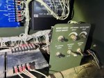
where would CB1 be located?If S10 doesn’t crank but you got voltage on #1 when s10 is pushed then it’s K2
this fuse has 25v on both sides of it and continuity so it’s goodOn a panel inside the cubicle
it’s a DC Circuit Breaker
I check continuity between #1 on the dead crank switch and the small wire on the starter solenoid and they are connectedOn a panel inside the cubicle
it’s a DC Circuit Breaker
Is this CB1?If S10 doesn’t crank but you got voltage on #1 when s10 is pushed then it’s K2
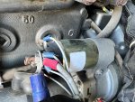
When I push the little center post the engine cranks over fine but no startIs this CB1?
K2 and yes S10 terminal 1 connects to K2 X1When I push the little center post the engine cranks over fine but no start
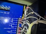
a littleDo you know on how to read a wiring diagram?


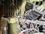
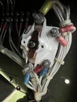
I found the MT4 but it was not as simple as the diagram made it seem as the S10 and the MT4 are not even close to one another. In fact it is hidden away behind a panel making it very hard to find when looking for. Yes it was labeled, however I am barely able to get my head in there and how I actually found it was that I took a photo and then I could see it more easily. This is why asking for help is often better than scrounging around for the unknown as I would have never seen it elsewise especially when the diagram has it as a 4 post unit and in reality it is a 2 post unit.You wrote:
problem is a diagram is not a 3D representation of the items plus the harness has a million little wires and the items are not labeled as per a number like CB1
The markings are there. You need to look closer.