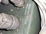
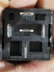
Thats the right Special Relay box. I have never seen on wired in red wire. Who rewired it? Or did it come that way?
You wrote:
I'm pretty sure it's the correct special really box. The static Exciter and voltage regulator are brand new and solid state and shouldn't have a problem. I should be getting a signal through my d-pin J 9 connector when starting correct?
(Correct. You should be getting 24 VDC.) Because I'm not getting any voltage from my d-pin. I believe if I get power to my D-pin the static Exciter would work. I did buy it from Oshkosh and it's been tested and proven.
My D-pin should have voltage when I start the machine I believe correct?
(Yes) I'm not sure if it's
DC or AC voltage though. But I definitely don't have any voltage there. Just trying to verify I should have power at the d-pin when starting. Thank you Gordy any other test procedures you can think of would be great. Thank you a ton! Gordy
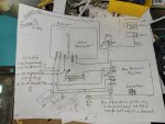
This would be how the A11 would normally send voltage to the G1 (after the inital excitation came to the G1 from the S9
IF, there was a A11 in the set. But your solid state rig is an unknown to me. If the S9 and special relay box are good, then all it leaves is your new exciter/volt regulator.
View attachment 896080