• Steel Soldiers now has a few new forums, read more about it at: New Munitions Forums!

  • Microsoft MSN, Live, Hotmail, Outlook email users may not be receiving emails. We are working to resolve this issue. Please add support@steelsoldiers.com to your trusted contacts.


Rebuilding the Injection pump

stb64

Member
162
15
18
Location
hohenfels germany
Honestly I don't know why you are so concerned with the droop screw anyway.
Rustystud, I am not ''concerned'' with the droopscrew, I simply asked for clarification.
You made two statements:
That the droopscrew :
1. helps add fuel and 2. prevents excessive fuel delivery
I fully agree with number 2, but do not understand how the droop screw could ever ''help add fuel''.
It is clear that these are two things that are exactly the opposite.That's what my question, still unanswered BTW, was all about.
I am a certified diesel mechanic, so there is no need to explain to me how the governor functions, I learned that decades ago.
I am very familiar with bosch injection pumps, so you will not have to explain the principles of operation.
You can go directly to the droop screw and tell me how it causes what part of the governor to move in which direction in order to add fuel.
Now since you were an apprentice at M.A.N. then you should realize that since the stop plate is a "curved" and not straight piece of metal that at times the droop screw will come into contact before the "cam" will. That was explained in the PDF of the last post I gave you.
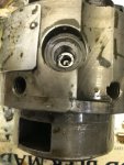
I know exactly when and under what conditions the droop screw comes into contact with the stop plate, and when the smoke limit cam does, but neither do I see how having been an apprentice at m.a.n. should make me realize the stop plate is curved, nor how it should be related to the FDC, and I could not find such explanation in the pdf either.
What I did see (and expected) is that the stop plate in the picture has two separate contact surfaces for the smoke cam and droop screw, having slightly different angles.
What I also see is that the pump in the picture is not a multifuel pump, and does not have a FDC. The governor operates on the same principle, however.
The code G pump's (LDS427-2) stop plate is perfectly straight. Smoke limit cam and droop screw are close together, and share the same contact surface.

The stop plates in the other multifuel injector pumps do also have two separate contact surfaces at slightly different angles.
If at all, the stop plate is rounded only where the 2 contact surfaces meet.

If you have bypassed the FDC like most people then it really has no more function for you
According to You, a droop screw ''has no more function'' with the FDC bypassed, as there are no more pressure changes, and the stop plate no longer moves, no longer causing surging.

My explanation, back in post#109, of how the FDC works :
''The pressure inside the FDC only changes when a different fuel is used.
The pressure inside the FDC is the same regardless of engine speed, and does not change during engine operation.''

Differs from yours:
''I think I know what the problem is here. Your not taking into account that the stop plate moves during operation. It is not stationary, but slides up and down according to fuel pressure.''''The stop plate is continually being adjusted according to fuel pressure at that time. Since fuel pressure is adjusted according to engine RPM then that means the FDC is constantly adjusting''

Well, got the tm out, and found this:
''The fuel supply is admitted to a pressure regulating valve where the supply pressure is reduced to a constant regulated pressure over the engine operating speed and load range''

This means the stop plate does not move during engine operation, and even if it did, it would only change maximum load fuel by an negligible amount, between the full load gasoline position, and the full load diesel position.

So your explanations did not answer my question yet.
Oh, and don't get me wrong.
Please keep in mind that my questions are of purely technical nature.
I truly appreciate Your threads. Lots of useful step by step information and heads up even for more experienced mechanics.
 

rustystud

Well-known member
9,071
2,387
113
Location
Woodinville, Washington
Well, got the tm out, and found this:
''The fuel supply is admitted to a pressure regulating valve where the supply pressure is reduced to a constant regulated pressure over the engine operating speed and load range''

This means the stop plate does not move during engine operation, and even if it did, it would only change maximum load fuel by an negligible amount, between the full load gasoline position, and the full load diesel position.

So your explanations did not answer my question yet.
Oh, and don't get me wrong.
Please keep in mind that my questions are of purely technical nature.


View attachment Scan0190.pdfView attachment Scan0191.pdfView attachment Scan0192.pdfView attachment Scan0193.pdf

First off the fuel pressure is not set at one regulated pressure. If you have a pressure gauge on your filters you can see that for your self. The TM says the pressure range is 30 to 60 psi. That is not a set pressure."
Second, the droop screw helps keep the engine from surging by keeping the "fulcrum" from moving back against the governor pressure, thus keeping the fuel pressure higher through the control rod. In the TM there is a full explanation of this. As far as the stop plate not moving, read these pages I posted here. It does not move much but it does move. Now just stop and think for a moment. The compensator has a piston that has a spring on top. According to you this piston will not move no matter the pressure against it. That is just wrong. The amount of movement is limited due to the two other pressures acting against it, but it still will move according to the main fuel pressure.
You say your only asking all these questions for purely technical reasons. At this point I think your just wanting to argue and I don't want to. You can read the TM yourself and come to your own conclusion. This thread was about rebuilding the injection pump, not a dissertation of the functioning of the injection pump and it's governing system. If that's what you want then start another thread. As it is I have spent way to much of my time going over all my injection pump manuals trying to find a good answer for you. There are several more pages I could up-load but I'm tired of this now. Oh, my comment about you being an apprentice was I assumed you could see in the manual that the stop plate was curved and could figure out for yourself what it meant. Nothing more.
 

rustystud

Well-known member
9,071
2,387
113
Location
Woodinville, Washington
View attachment Scan0194.pdfView attachment Scan0195.pdfView attachment Scan0196.pdfView attachment Scan0197.pdf

I think we all got side tracked with the whole FDC thing so I will try one more time to explain. Now before you say that is not the same pump, take a look at it's function. It is the same principal and almost the exact same design as our pumps.
First off forget the FDC and just think of the stop plate as fixed. You can see that the droop screw helps keep the governor "in check" during acceleration and deceleration, and still allows the Turbo time to spool-up preventing smoke.
In the first page you see that the droop screw does add fuel. The next three pages shows how the droop screw actually decrease's fuel. In many ways the droop screw is "By-Polar" . First acting one way then acting another depending on the situation. Also look closely at the fulcrum lever. It does not move linearly but actually moves in an elliptical fashion. Also the operating lever is not physically connected to the fulcrum but is connected by a spring which allows for a unique movement to the fulcrum lever. Then there is the "spyder" connection to the governor itself from the cam shaft. It allows the governor to lag behind the actual speed of the engine. All these factors add up to the total function of the governing system allowing the droop screw to have many functions.
Now when you add in the FDC you get a totally different function for the droop screw since the stop plate does move.
So now I'm done with this explanation and if you want more answers then study the TM's for yourself. Who knows, I might be full of Sh!t and then you can prove me wrong. Just be sure to actually use real information like pages from the manuals and not just useless words with nothing to back them up with.
 

rustystud

Well-known member
9,071
2,387
113
Location
Woodinville, Washington
So with the FDC bypassed the droop screw would need to be turned clockwise to reduce surging?
Depends. Is the engine surging now ? If it is then you would need to either increase fuel or decrease fuel. So since we don't know you would have to try clockwise 1/4 turn and if that didn't help then turn it back 1/2 turn. Either way it is trial and error adjusting.
 

rustystud

Well-known member
9,071
2,387
113
Location
Woodinville, Washington
I just want to say one more thing about the FDC and it's function. Think of it as a "voltage drop" compensator. If you have a long electrical cable you will end up with voltage drop across the ends. So what the FDC does is build in a compensation for this voltage loss. Just like copper has one resistance per foot and aluminum has another so does gasoline compared to diesel fuel. So at a given pressure and flow of fuel we will have a different "resistance" for gasoline compared to diesel fuel. Since diesel fuel has more BTU's of energy compared to gasoline it will get a higher resistance to bring it down to the gasoline's level. This is one reason most people just eliminate the FDC completely. That and the fuel leakage problem.
Now as to how much movement the stop plate has, I don't have an answer. But I do plan on making my own tester later on and then I can determine if and how much movement there really is.
I know I have been a little testy answering some questions here. The reason is I did not want this thread to degenerate into an argument session. It was to be a stand-alone rebuild thread that I hoped could be sealed and put into the stickies. In fact I was hoping the moderators could go back to post #98 and delete everything after that and then seal this thread.
Then if anyone wanted clarification on any pump matter they could start a new thread and all discussions and arguments could be held there.
 
Last edited:

Beyond Biodiesel

Active member
373
36
28
Location
Prescott, AZ
Thanks, Rusty, and others for this valuable thread. I have 2 questions regarding the injector pump, which might be off-topic for this thread.

1) I found the motor oil level in my deuce was rising, and I asked on another thread, and was told the probable cause was the hydraulic head (HH) had to be resealed, so I ordered a seal kit, and resealed it. I found no change in the chronic rising of the crankcase oil level, so I ordered an unused and newer model of the deuce IP. I found the chronic rising of the crankcase oil level continued.

So, the question is: "Since I do not run gasoline in my deuce, other than it blended with waste oils, is it reasonable to conclude that the fuel making its way into my crankcase is coming from the oil line that goes to the IP from the engine oil line? If so, how does everybody feel about disconnecting the oil supply to the IP, and connect the IP's oil line to the fuel return line, assuming that diesel fuel has sufficient lubricity to properly lubricate the IP? I I think is most likely does.

2) My second question is" I made the mistake of following a thread that was here, and does not seem to be anymore, which recommended cranking up the fuel flow of the IP to increase power of the deuce engine. In the process, I ended up breaking a component of the FDC causing my deuce engine now to run at high idle, which surely uses a horrific amount of fuel.

So, the question is: Can I simply remove the top cap of the FDC to pull the parts assembly of the FDC off my old injector pump and pull the cap off the top of my new IP and use tweezers to pull out all of the FDC parts that fell into the IP, and then put the FDC assembly from my old IP into the new IP, and expect to have fixed this problem?
 

cattlerepairman

Well-known member
Steel Soldiers Supporter
3,167
3,069
113
Location
NORTH (Canada)
Beyond, there are 4 ways fuel can make its way into the crankcase. The HH is one of them.


If you replaced the IP completely, you also replaced the booster pump, so you can likely eliminate that as the source. Flame heater, FDC?
 

Floridianson

Well-known member
Steel Soldiers Supporter
7,390
2,432
113
Location
Interlachen Fl.
The oil line that comes off the block and goes to the IP feeds the IP the oil it needs. Leave it alone or as said they both could stand to be replaced if never done but has nothing to do with fuel in oil.
I do not know what you have done to your FDC and dropping parts inside? What did you do? Is your FDC bypassed if not it needs to be done. Yes booster pump is a good place to get fuel into the oil if you have done replaced O rings in Head and fuel control unit assembly. Also do away with the flame heater and block off flame heater fuel line.
 

Floridianson

Well-known member
Steel Soldiers Supporter
7,390
2,432
113
Location
Interlachen Fl.
Now I' even more confused:

The droop screw, which can only rest against the stop plate, and keep the fulcrum lever from moving further towards the ''increase fuel'' position, does two things that are exactly the opposite?:


(Floridianson)
Makes sense:

The pressure inside the FDC only changes when a different fuel is used.
The pressure inside the FDC is the same regardless of engine speed, and does not change during engine operation.

How can the stop plate move during operation? And how would movement of the stop plate cause surging?


This already is my understanding of the droop screw's, and governor's, function. It is, basically, what i learned back when I was an apprentice at M.A.N.


Thanks. I'll see if I can access the manual at work.
Just for smitts and giggles I looked at the TM. Correct FDC only should move when fuel changes and on start up. Now if we go by the TM fuel goes to a pressure regulating valve as per TM that is 20 /21psi. So even at idle where we have a minimum of 30 psi or high idle 60 psi it will not be over 20 / 21 psi in the servo not 60 psi at servo.
 

Attachments

Last edited:

Beyond Biodiesel

Active member
373
36
28
Location
Prescott, AZ
Beyond, there are 4 ways fuel can make its way into the crankcase. The HH is one of them.


If you replaced the IP completely, you also replaced the booster pump, so you can likely eliminate that as the source. Flame heater, FDC?
I've replaced the injector pump, which means the booster pump has been replaced, and the flame heater died, so it has been removed, but I don't see how it could be a source of fuel entering the crankcase.
 

Floridianson

Well-known member
Steel Soldiers Supporter
7,390
2,432
113
Location
Interlachen Fl.
As per some you can check the booster with just the in tank pump and it's low pressure if the seal is real bad. TM tells us we need to push 60 psi through it to check for a failing seal with it removed from the IP. Unused to me is old rubber and still might be your cause. As for you asking about replacing inside parts on your installed IP. If you have one on the bench you could take the four bolts and lift the FDC up a bit and see if the rod that connects the wedge plate to the servo has a locking pin. I can not remember. If not then you should be able to disconnect the FDC servo from the wedge plate and see inside. I am guess you broke the stud off of the main fuel wedge plate. It might be tuff to replace it when IP is still installed on the truck. I have never tried it but I also have never broken the twin nut stud. It has been done and I even sent the OP the part to fix his broken wedge plate stud but I did not hear how he did it. I do not know why some of my post is under lined. aua
 
Last edited:

brianp454

Member
572
11
18
Location
Portland, OR
I'm rebuilding a spare hydraulic head to swap it and the booster pump onto my engine when I'm confident they are as good as new. There's some kind of sleeve down inside under the 12 point screw that I haven't been able to fish out and clean. It seems to be held in by the oil on the back side. See pic. It turns with no force and a magnet cannot pull it out. Anyone ever removed this? What's behind it?
 

Attachments

Top
AdBlock Detected

We get it, advertisements are annoying!

Sure, ad-blocking software does a great job at blocking ads, but it also blocks useful features of our website like our supporting vendors. Their ads help keep Steel Soldiers going. Please consider disabling your ad blockers for the site. Thanks!

I've Disabled AdBlock
No Thanks