• Steel Soldiers now has a few new forums, read more about it at: New Munitions Forums!

  • Microsoft MSN, Live, Hotmail, Outlook email users may not be receiving emails. We are working to resolve this issue. Please add support@steelsoldiers.com to your trusted contacts.


Ross HF54 Power Steering in my Deuce

Seth_O

Member
625
7
18
Location
Sac CA
I have been researching and preparing to install PS in my deuce for a while, so I know there are many, many threads covering it. Some of which are very good, but it seemed that my particular experience was a bit unique, so I thought it might be worth it to share how I tackled it for my truck.

Any post I could make would be incomplete without a huge thanks to Gerhard who provided lots of assistance and counsel - I literally could not have completed it without him. I also owe Jason a thanks as well for his thoughts and insight.

I originally chose to do the Ross HF54 because it goes inside the rails and has been done so many times before with good success. I figured I could piece it together cheaper than a ready-made kit for the saginaw which is the other option I considered. The reality is the saginaw kit that Tom sells would have been at most the same cost as piecing together the Ross setup. If you don't have the reluctance to cut up the fender that I have, then I would recommend going the pre-made kit route. It would certainly save A LOT of time, frustration and potentially expense.

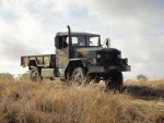
All that being said: I started with a bobbed '67 deuce on stock tires and rims. I've been driving it for a couple of years and really enjoying it, but even with the stock 9x20's its a lot of work to steer as I'm not a big guy. It's also impossible for my wife to drive in an emergency, and when it's loaded down there's no turning the wheel unless you're under way. I would love to someday put 395's on it; all of this lead me up to power steering for the truck.
 

Attachments

Seth_O

Member
625
7
18
Location
Sac CA
About a year ago I ordered a used 4-port Ross HF54 PS gear from Van DerHaags in Des Moines Iowa. I wanted 4-port in case I ever decided to install a steering ram. I think thats unlikely, but if it ever happens I want the option. There was no additional cost for the 4-port vs the 2, and Van DerHaags had one that looked to be in decent shape. I was careful to order one with the 4 bolt mount. Mine came from an '80 LN700. I paid $250 for the box, and it shipped with the pitman arm attached. I was shocked at the overall size of the thing. It's ruddy huge. In later research I found out the box weighs almost 70lbs. Crikey. After it arrived I searched around online for a rebuild kit. I wanted to make sure I got any maintenance done in advance - I knew I wasn't going to want to pull it out again later because of a leaky seal. The best I could find was gates steering kit 147966, found at carpartsonline.com for $70. It comes with all the seals and soft parts, and some of the hard parts as well (cotter pins, locking washers, etc.)

Ultimately I was really glad I did it. Gerhard provided me with the full .pdf for the gearbox which made the rebuild a snap. It was literally a 90min project, and I found one or two blown seals internally. I cleaned it up as I went along. The only tricky part I found was setting the bearing load for the mainshaft. I did find that the star bolts on the main shaft cover were completely shot so I had to drill them out. Turns out its the same price to order the package of 10 new bolts, vs buying just two. Accordingly I have 8 extra bolts, so if you need one - let me know.

With the box rebuilt, I cleaned it up and shelved it for a while. It was time to move on and work on to the pump.
 

Attachments

Last edited:

Seth_O

Member
625
7
18
Location
Sac CA
I ordered a used 5-ton MF pump from kublos with the adapter attached. Ken is one of my favorite people to buy from - he's always straight up and has good prices. It's a bummer being on the opposite side of the country from him though.

He said he had a take-off pump and adapter that he would make no commitments on. At the same time Gerhard pointed out to me a brand new Vickers pump on ebay that was the right kind for the multifuel (this particular one was Vickers VTM 42-50-45-15 MF L1 14 SF.) I paid $100 for the used from Kublos, and $150 for the new pump from ebay. When the used pump arrived I started by taking it apart. The inside was pretty well trashed, looked like it had been run for a while w/o any fluid in it. The walls were shaved down, and the mainshaft was torqued over and bent. I was ok with it though, as I had really purchased it for the adapter and I knew I had a new pump on the way.
 

Attachments

Last edited:

Seth_O

Member
625
7
18
Location
Sac CA
So about a month ago I finally parked the truck in the driveway, and started taking everything apart. It was a surprisingly quick take-down; flasher off, disconnected the lights, and removed the fender. I had the truck parked on a slight slope on gravel, so I wasnt comfortable taking off the tire and decided I would just work around it. I cut the steering shaft at the box, and pulled the wheel and shaft out the cab. I wasnt sure what length I needed the shaft to be, so I left it as long as possible.

I removed the pitman arm and drag link, then took the gear cover off and removed the wiring for the horn. I pounded out the sector shaft and removed the box. No need to move the engine at all.

I did take the time while I had the gearbox out to replace the seal on the booster pump in the IP. That thing is such a ruddy pain to get to, I didnt want to have to get in there again later.

With the gearbox out of the way and everything exposed I took the time to clean the area up as best as I could. I removed the factory stiffener plate and ground out one of the rivets from the front cross-member support. I wasn't comfortable removing more than one of the rivets on the x-member support.

I went to the steel yard and picked up a piece of remnant C-channel, 8" wide and 21" long and 3/8" thick. I was hoping to use it as c-channel, but quickly realized I would have interference from it on either the pitman arm or the drag link. Accordingly I ended up cutting the lower arm of the c-channel off before I used it. I used c-clamps to pin it to the frame and mark two holes on the back side from the existing holes in the frame. I drilled those out and pinned it to the frame so I could mark for measuring and cutting the large hole to mount the box.
 

Attachments

Last edited:

Seth_O

Member
625
7
18
Location
Sac CA
I used the measurements Gerhard provided and scribed a mark measuring back 8 3/16" from the center of the front spring hanger and up 3 2/3" from the bottom of the frame. I punched it and drilled it out with a 3 5/8" hole saw I got from Home Depot. The Ross HF54 doesn't sit flush with the frame so if you don't drill the hole out this large, the box wont mount correctly. This also allows you to get to the seal under the mainshaft cover if you need to service it in the future.

I didn't have the ability to turn the existing drawings and measurements I found online into a template to mark where to cut the HF54 mounting holes, so I placed the box on my workbench on a 30* angle to simulate the angle it would need once mounted. I then used stiff cardboard to create a template for the mounting holes. I transcribed those holes to the frame and drilled them. This allowed me to hoist the box into place and align the holes in the frame with the holes in the box by sight and determine how much of the top part of the frame I needed to remove. I took it out bit by bit, until it was just enough to fit the box in w/o rubbing on the frame.

This also allowed me to see my first real problem. With the frame removed sufficiently, my box still wasn't sitting flush against the frame, something at the rear of the box (the front of the truck) was interfering. I checked all my measurements for the umpteenth time and tried to crawl under the truck to see if I could get a visual on the issue. The box was hitting the x-member support where it attached to the frame. This was a head-scratcher for me so I checked my measurements yet again.

I emailed Gerhard, and he confirmed that the measurements were accurate and I wouldn't have any problems, unless I for some inexplicable reason happened to have the older, A1 style cross-member on my truck. So I started looked around online and found a picture Gerhard has posted that happened to show his front x-member. Sure enough, it was different than mine. This is probably the only thing I would have done differently were I to do it all again, I would have moved my placement back an additional 1-2" to clear the front x-member because of my A1 style support.

By this point however, I had already drilled the holes in the frame and stiffener so I couldn't move it. Accordingly I pulled out the pen and marked the parts on the x-member that would have to go. I pulled out the grinder and cut out as little as possible, I had to remove some of the head of one of the bolts, and some of the material of the support itself. With the additional material removed, the box slid into place and bolted in nicely. I then drilled out the remaining holes to bolt the stiffener to the frame and final-installed the box and bolted the stiffener in all the way. Then I danced a jig because the box was in - yay!
 

Attachments

Seth_O

Member
625
7
18
Location
Sac CA
Next I cut out the radiator shroud from around the front of the IP so I could fit pump on. I used the cover-plate to determine pump orientation and then finagled it into place. It was a bit of work to get it in there, and I was surprised that the pump didnt just slide into place. I fiddled with the gears for a bit and jockeyed it around and it eventually went in. With the pump in place I grabbed a piece of semi-stiff tubing I had laying around from redoing my injector return lines and mocked up the pressure-side hose (from the top of the pump to the bottom of the gearbox) so I could get a measurement.

With the measurement in hand I took the fittings off the box and the pump into a shop that makes pressure hoses. Turns out the suction and bypass openings on the pump are pipe thread, the pressure is #8 SAE the fittings on the box were AN. I got a plug for the pressure relief valve on the pump, and two plugs for the extra two ports on the gear. The suction line on the pump was 3/4" and I got a 3/4" 90* to barbed for that. The pressure line was 3/8", 90* as well.

I went to the junkyard at this point and dug up an oil cooler off a truck with 3/8" lines on it. I cant remember what I took it from, but they are all over. Once I was back from the hose shop I final installed the pump, and hooked the pressure line up from the pump to the gearbox, it fit perfect! No rubbing or contact anywhere.
 

Attachments

Last edited:

Seth_O

Member
625
7
18
Location
Sac CA
While working on this I was trying to work out in my head how I was going to connect the steering column, and what I was going to do for a steering shaft. I looked all over and found lots of solutions, but they all seemed overly complex to me, or required using a gamma goat column or some custom steering shaft setup. This kind of thing makes me nervous. I cant afford to buy parts I am not going to use, so I really need to hold something in my hand to make sure its what I need and its going to work.

I spent a lot of time poking around online trying to figure out what I wanted to do. I took a bunch of measurements of the column, and realized that the OD of the steering shaft itself is 1". The input shaft on the steering box is 13/16" - 36 spline. While researching I found a Borgeson joint that was 13/16-36 x 3/4" DD (borgeson 14940, $80 at a local steering shop), a 2' 3/4" DD to 1" DD collapsible shaft (borgeson 450024, $75) and a 1" smooth to 1" DD joint (borgeson 15268, $77). With this I would be able to weld the smooth bore end to the steering shaft and connect it to the DD collapsible shaft. The other end of the shaft would slide into the joint that connects to the box.

The only other problem I would need to overcome would be holding the shaft centered in the steering column. I spent a LOT of time looking for a bearing that would fit over the shaft and inside the column. I could get either the OD or the ID, but not both. I eventually settled on a graphite bushing from McMaster Carr (PN 9368T211, $21). It was an exact fit. It was more than I wanted to spend, but it was the best option I could find for durability.

I figured there was a very small possibility the bushing could migrate it's way up the column from the repeated turning, so I cleaned the column up really well, and laid a small bead of weld down above the bushing, leaving enough room for the column to compress on the spring mounted at the wheel. I happened to have two hole drills exactly the same size as the OD of the shaft, and the OD of the column, so I cut out a piece of donut-shaped steel to weld onto the end of the column to hold the bearing in place and seal it in there. It worked perfectly.

In retrospect I probably could have done just that cap piece and been ok. The shaft doesnt turn that much or that quickly that its going to damage the shaft. But its in there now, and will alleviate any problems that might have arisen.
 

Attachments

Last edited:

Seth_O

Member
625
7
18
Location
Sac CA
Once I had that worked out I pulled out a steering column support I ordered months previously from Red River parts ($15) and measured and mounted it inverted on the firewall in the engine compartment. I welded on the borgeson joint, and then installed the column. Then I measured and cut the collapsible shaft and installed it as well.

While working this stuff out, I was noodling on how I wanted to mount the reservoir and what I wanted to use. I had a 5-ton reservoir I had purchased some time before, but it was ruddy huge and there was no good way to mount it. I knew the gear needed a reservoir with a filter, so I did what I always do when in doubt and turned to the internet. Jason came through for me here and pointed me towards the one he used in his setup with good success (Nelson 91048A, $75 at finditparts.com) Since I was putting in all used and rebuilt parts, I went ahead and ordered an extra filter, figuring I will replace it soon (Nelson 87904M, $20 from ebay.)
 

Attachments

Seth_O

Member
625
7
18
Location
Sac CA
With that all done I was able to start putting original pieces back on, and it started looking like I was making progress! I measured the fender carefully for where I would need to cut it slightly to allow for the bracket on the steering box. I cut it as closely as I could and tested the fit. It required a little bit of enlarging, but not much. I remounted the fender and hooked all the electrical back up. I installed the flasher again, and found where I wanted to put the oil cooler. I decided it would fit best over the vents on the fender wall, and the steel on the fender is plenty strong to support it. I worried briefly about something hitting the underside of the cooler and putting a hole in it, but with the direction of the vents the truck would have to be in reverse to kick something up into it. Plus the cooler I got has really thick steel, almost as thick as the fender sheetmetal itself.

With the fender on I was able to find everywhere I hadn't allowed enough clearance. There were several places :(
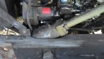
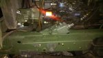
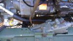
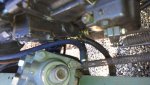
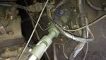
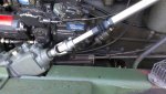
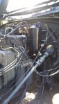
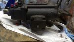
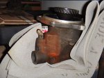
. I had to repoint the suction line on the pump down to clear the grill support and I had to repoint the pressure side line from the pump as well. After getting everything in the right spots I did a final tighten on the lines and fittings. I had ordered the reservoir and was waiting for it to arrive, and in the meantime had installed the hoses and fittings from the pump to the gear to the cooler.

I was also starting to worry about how I was going to connect the pitman to the knuckle, I didnt have an answer for that one yet and it was starting to stress me. I was hoping to find a clever way to connect the pitman arm to the tapered ball stud on the knuckle using the stock drag link. I futzed around with A LOT of different ideas and couldn't make anything work.

Ultimately what I ended up doing was going back to the steel yard and picking up a 11" piece of 1.6" diameter steel bar stock. I took it into a machine shop and had them drill one end out to 1 3/64", and the other end out to 15/16". I then filed the furthest right spline on the pitman arm so I could index the arm one spot to the right. I asked the machine shop to thread the large opening 1.125 -12 left, and the small end 1.00-16 right. Unfortunately those are non-standard sizes. They happen to be however, just the right sizes for the TRE's that fit the pitman arm and the knuckle (once you remove the tapered ball stud.) I ordered the pitman arm TRE (ES187L) from Nicks Truck Parts for $32. The knuckle TRE (ES304R) came from Nicks for $31.

So I jumped on Ebay again, and found my taps for about $30 ea and I took them to the machinist who was then able to tap the drag link for me.
 

Attachments

Last edited:

Seth_O

Member
625
7
18
Location
Sac CA
My reservoir arrived, and it looked great. It came with the mounting hardware and was ready to go. I took it with me into home depot and picked out the fittings I needed. The only downside to it was that the output opening (so going to the suction side of the pump) was only 1/2", vs the 3/4" suction fitting on the pump. No way around it, so I just adapted it up so I could use the larger line. Turns out that 3/4" oil-safe tubing is very expensive, like $7/ft. Ouch.

The reservoir fit almost perfectly on the open nuts on the firewall above the fuel filters. Almost. So I pulled out the grinder and some stock steel I had laying around and built a quick bracket using the existing nuts on the firewall. It worked out great, and the reservoir mounted up nicely. That allowed me to finish up the wet-side installation of the power steering.
 

Attachments

Seth_O

Member
625
7
18
Location
Sac CA
So today I finally took it for a short spin. The power steering is incredible, so much easier to drive! The box and pump move the truck around no problem. I found that I used almost exactly 4 qts of fluid, using the reservoir and cooler. I had no problems adjusting the steering (thanks to the drag link that is threaded for adjustments) to get full range. Bleeding the pump and box was pretty easy with the pitman arm off. I found the steering to be very responsive and sensitive. In the past getting the truck into his parking spot was a series of 4-5 pt turns. Today there was a truck and trailer parked across the street in the spot I normally use to execute my 4-5 pts and I was still able to get it parked in the first go, with no back and forth. It makes driving the truck so much more enjoyable. I wish I would have done it a while ago.
 
Last edited:

ducer

Member
297
1
18
Location
Ober, indiana
Nice write up and pictures![thumbzup] Very nice and clean install, looks almost factory. One thing I would have done differently though is where you have sharp corners where you cut the frame I would have radiused them to avoid stress fractures in the corners, otherwise excellent install! No, I don't mean to nit pick. I can't stress enough how much I like the install.
One question I have is what did you do about the horn wire?:doh:

Denny
 

rustystud

Well-known member
9,071
2,388
113
Location
Woodinville, Washington
Great JOB ! The one question I have though is how do you secure the draglink to the ends ? Do you use jam nuts ? Also what is the part number of the steering column support bracket you used ?
Thanks.
Greg.
 

JasonS

Well-known member
1,643
126
63
Location
Eastern SD
Great JOB ! The one question I have though is how do you secure the draglink to the ends ? Do you use jam nuts ? Also what is the part number of the steering column support bracket you used ?
Thanks.
Greg.
Slit the ends of the drag link and get an off-the shelf tie rod clamp from NAPA.
 

Seth_O

Member
625
7
18
Location
Sac CA
Nice write up and pictures![thumbzup] Very nice and clean install, looks almost factory. One thing I would have done differently though is where you have sharp corners where you cut the frame I would have radiused them to avoid stress fractures in the corners, otherwise excellent install! No, I don't mean to nit pick. I can't stress enough how much I like the install.
One question I have is what did you do about the horn wire?:doh:


Good thought on the rounded edges, were I to do it again I would have spent more time on the frame cutting. It was a tough area for me to work in.

Currently the horn wire is capped. I plan on putting a dash button on. However, at some point in the past the truck was converted to an electric horn, and it sounds a lot like the horn on my 4yo's Big Boys Power Wheels. I'll wait to install it until I have an air horn. It's embarrassing :(
 
Last edited:

Seth_O

Member
625
7
18
Location
Sac CA
Slit the ends of the drag link and get an off-the shelf tie rod clamp from NAPA.
I tossed a couple of ideas around. I thought about cutting a small piece of threaded end off each side of the drag link (I made it plenty long) but I don't really trust jam nuts. I have more time than money right now, and a variety of steel laying around, so much like Jason recommended I slit the ends with the grinder and welded up a couple of clamps. I didn't get around the taking pics of those, at that point I was too close to driving to stop for pic's ;-).

The long-term plan is to pick up a couple of off-the-shelf clamps from either Napa or the salvage yard. The home-made ones should hold until then though.

Not sure on the column support bracket, I just called Red River Parts and told them I needed the column support bracket from the dash.

Also, not in the original post, but I was worried about air and water getting in around the column through the firewall (my cardboard cover has long-ago deteriorated.) I went to WalMart and picked up a cheap car floor mat and traced out the shape of the bracket and marked the mounting holes. I then put the bracket on the column at the very end, so that the plastic was just touching it and cut the top edge of the plastic where the column touched it. I slid the column forward slightly and cut down the sides, then slid it further along and cut out a little more around the sides, then a little more to get the bottom. In this fashion its a snug fit around the column despite the oblong shape because of the ~30* angle.
 
Last edited:

Seth_O

Member
625
7
18
Location
Sac CA
Now that the project is pretty well wrapped, I have some extra parts and project-specific tools laying around if someone needs them:

* the star screws for the mainshaft cover of the Ross HF54, I have several extras
* a 5-ton PS reservoir, I initially planned on using it but couldn't make it work
* a RH tap, 1.00-16
* a LH tap, 1.125-12

If you need any of this stuff, feel free to shoot me a PM. Extra parts I can sell cheap, tools I can lend.
 

Stan

Member
488
7
18
Location
St.Louis, Mo.
Nice work and description. This past spring I did this to a M37 using parts from Snake River 4x4. Very similar process. Not having a good option for the horn and not wanting a button on the dash I improvised. I ran the wire inside the column as orginal and then let it exit at the u-joint. Leaving enough wire loose so that it can loosely wrap the shaft when you turn. So far so good.
 
Top
AdBlock Detected

We get it, advertisements are annoying!

Sure, ad-blocking software does a great job at blocking ads, but it also blocks useful features of our website like our supporting vendors. Their ads help keep Steel Soldiers going. Please consider disabling your ad blockers for the site. Thanks!

I've Disabled AdBlock
No Thanks