Hmmmm, I finished painting the cab today and started to hook up the steering, when all of a sudden it hit me like a brick....I finally figured out why they use a different type of yoke for the steering stub shafts than for all the other driveshaft setups!!!
The yokes, that I got for my steering, were NOT the steering type yokes.
I always figured the reason for the clamping bolt and the corresponding groove in the shaft on the steering yokes were for added safety, so the yoke could not slip off the shaft even if the bolt were to come loose.
Since in my setup the stubshafts were "trapped", I felt that securing the yokes on the shafts with the set screws, using locktite would be more than sufficient.
What I did not think of, is the fact that on most transmission shaft installations the shaft only gets torque in one direction. This lets the yoke settle against the keyway and the set screw is there to keep it all tight.
On a steering stub shaft on the other hand, the torsional forces may alternate back and forth thousends of times, while driving down a bumpy road! It is then pretty easy to imagine, that over time the set screw even thought locktited in place, will start to wear in to the shaft and in the process letting the yoke develop play within the limitations of the keyway!
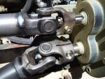
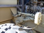
Thus the reason for the clamping bolt on a steering yoke. In addition to clamping around the shaft tightly, it is also situated at a 90 degree angle from the keyway, so it can tighten up any play in the keyway slot!
Anyway, for me it was back to the drawing board. I was able to "cannibalize" two steering yokes with a 1" bore from my old HEMTT cab, but I could not find a 1 1/4" bore steering yoke.
Luckily my set screw type 1 1/4" yoke had a lot of "meat" on the collar and I was able to machine the bolt hole and the surfaces for the bolt head and nut in to it. I then used the chop saw to cut the slot and make it in to a clamping type steering yoke.
Catastrophy avoided!!

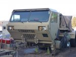
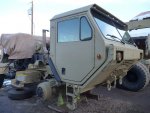
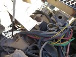
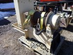
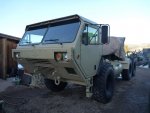
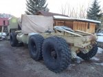
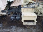
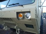
Here are some pics of the new (and hopefully improved) steering setup and the painted cab.

 Good to know that factoid for any future engineering. I built a 4x4 and used to wrong joints. That 4x4 is a memory now.
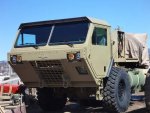

") ).
).