• Steel Soldiers now has a few new forums, read more about it at: New Munitions Forums!

  • Microsoft MSN, Live, Hotmail, Outlook email users may not be receiving emails. We are working to resolve this issue. Please add support@steelsoldiers.com to your trusted contacts.


Cut MEP-803a fuel return lines

warf

New member
8
11
3
Location
Arecibo, PR
Hello all,
I was hoping to enlist your help today.

I have read a lot of threads here, and though I have learned a lot of useful stuff, I have not read one with my exact problem.
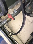
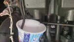
I found a diesel leak on my MEP 803A and its coming from what I think are cut fuel return lines:

IMG_3573.jpg

I am planning on replacing them with the ones recommended by Daybreak (CONTITECH) on this site anyway,
but the problem is I do not know where to hook them up. Do I need to connect to the fuel return line,
the fuel filter (like some generators) or do they go somewhere else?

IMG_3575.jpg

Thanks in advance,
Warf

PS This is my first post here and English is not my first language, so please bear with me.
 

Light in the Dark

Well-known member
Steel Soldiers Supporter
3,560
5,064
113
Location
MA
Welcome to SS. Take the sheet metal panel off the machine near the fuel inlet, and you will see exactly where the line terminates. It does pass through a clearance hole in the sheet metal, to end above the fuel tank. Very easy repair, and a great time to learn a bit about what runs where, and why.
 

warf

New member
8
11
3
Location
Arecibo, PR
Thanks for the reply.
The sheet metal you mention, is it the one that is on the top-left corner of the second picture I posted, the one in green?

I have more questions:

The fuel line showed on the second picture is coming from the Fuel Injection Pump. The cut ones are from the fuel injectors.
Do all three lines merge into one before they go into the fuel tank or does the tank have 3 connections for the three lines?
 

Light in the Dark

Well-known member
Steel Soldiers Supporter
3,560
5,064
113
Location
MA
The sheet metal on the top-left corner of what you posted is the back wall, separating the engine compartment from the fuel tank. It is behind that sheet metal, at the bottom, which I am talking about. If you look on the back of the machine, there is a removable panel at the bottom (just to the right of the fuel filler). Its got 5 bolts along its top edge, which connect it to the upper sheet metal. Just remove this panel (its all nuts and bolts, so pretty easy to do).

To do this repair properly, you are going to want to take the top sheet metal off (over the engine and radiator). Some bolts go into captive nuts (so nothing for you to hold onto, just unscrew them), but others will have nuts on the backside which you have to hold, while untightening. Be very careful when you undo the nuts and bolts along the top seam (separating the engine bay, from the part of the machine with the control box).... you don't want a nut to fall into the generator head (keep count of all fasteners!).

Once the top metal is off, you will be able to see the entire fuel line system. The line you photographed that is cut, runs along the top of the engine block (and has small Ts that connect to it along the top of the engine). You are going to want to remove every last inch of this return fuel line when you do the job. Take your time, and do it right. Its not a hard one.
 

Guyfang

Moderator
Staff member
Moderator
15,826
21,971
113
Location
Burgkunstadt, Germany
Look at TM 9-6115-642-24P, page, (PDF reader page # 26) Remove item 6 and 18.

Look at TM 9-2815-253-24P, PDF reader page # 29. There you can see where the hoses go, what gets hooked to them, like T connectors.
 
Last edited:

Ray70

Well-known member
2,354
5,010
113
Location
West greenwich/RI
Can't see exactly where your fuel lines are going, but something looks wrong in your pics. The fuel return line should go from the end of the fuel supply rail up to the first injector, then in-line T-fittings to each other injector then from the last injector's T-fitting ( where you show the diagonally cut line ) all the way back through the radiator support panel to the fuel tank.
In your 2nd picture it looks like the return line is going from the tank straight up towards the front of the motor ( to either the end of the fuel supply rail or 1st injector? )
If everything was hooked up correctly you would have a constant flow of fuel coming out of that slash cut line whenever the fuel pump is on!
 

Bmxenbrett

Member
602
29
18
Location
NY
I believe the cut line on top of the engine above the gen head goes to the return that goes towards the tank down by the engine oil drain valve in your second pic....so both of your lines in the pic, connect them together.

Daybreaks contitech part number is good and is about 25ft of hose. More than enough to do one 803a.
 

warf

New member
8
11
3
Location
Arecibo, PR
Thank you all for the replies.

Ray, I think you are right. The fuel line the is connected to the T-fittings is cut at both ends, I only posted one side only. I am going to take some pictures tomorrow and post them here to verify.
 

Ray70

Well-known member
2,354
5,010
113
Location
West greenwich/RI
I've bought a lot of the Continental fuel line on Ebay. look for "5 Meter roll Continental German 3.5mm Fuel/Vacuum hose Diesel TDI" I get 5 meters at a time for $29 and free shipping, cheapest I've found.

BTW, I see you're in PR. I've sold about 8 machines to guys who have shipped them to family down there and I hear things are very rough with the current situation. Hope you get your machine up and running quick and best wishes to everyone down there!
 

warf

New member
8
11
3
Location
Arecibo, PR
Hello all,

Sorry I took so long to respond, its been crazy at work. Here is how the fuel line is connected right now:

IMG_3583.jpg

These are the cut fuel return lines:
IMG_3574.jpg IMG_3573.jpg
If I understood you guys correctly, I should detach the hose from the fuel supply rail (circle #1), and attach the fuel supply rail to the cut line closest to the radiator fan (circle #4). Then, I should attach line closest to the generator (circle #3) to the line that goes to the tank (circle #2). Is that right?
Can I just yank the line from the fuel supply rail?
As far as how things are here in PR after Maria:
Things are getting better but we still have lot to do. There are still people with out power. A lot of people from the 50 Sates are helping with the rebuilding, and we appreciate it very much! But what worries me is that the power grid is kinda delicate still and hurricane season is upon us.
Thanks for asking.
 

Attachments

  • Like
Reactions: JRM

Light in the Dark

Well-known member
Steel Soldiers Supporter
3,560
5,064
113
Location
MA
Yes, you are going to want to disconnect the line from the end of the fuel rail. You can't take a shortcut back to the tank from here though... if you take the top sheet metal off, you will see that there are 4 plastic Ts on top of the cylinder heads where this line sits. To do this job right, you are going to want to replace each small section with new line, then drape down the rear of the engine (where your cut is now, near the dead crank switch), and past the battery, and through the rubber bulkhead fitting back to the tank.

Its a very simple job, just dont overthink it. Get the line, and allot 2 hours for yourself to move at a snails pace to track all fasteners and empty beer bottles. You will see its easy.
 

warf

New member
8
11
3
Location
Arecibo, PR
Hello all,

Just wanted to thank you all for the help/information. [thumbzup] I went ahead and replaced all the fuel return lines. Bought the fuel line recommended here (CONTITECH). Took the top off and the panel next to the fuel filler. It took me like three hours. I was tempted to try it with out removing the top off but I'm glad I didn't (its kinda cramped up there). I do recommend having a good pair of scissors or knife to cut the line.

When I lifted the top I was not paying attention and the spring, plate and seal came flying out. I put them in the order shown on figure 14 on TM-9-6115-642-24P but thats not how they were installed before. I'm assuming the person that put them together didn't put them right.

Once again thank you
 

DieselAddict

Well-known member
Steel Soldiers Supporter
2,481
1,878
113
Location
Efland, NC
When I lifted the top I was not paying attention and the spring, plate and seal came flying out. I put them in the order shown on figure 14 on TM-9-6115-642-24P but thats not how they were installed before. I'm assuming the person that put them together didn't put them right.Once again thank you
Good job and also good thinking about following the manual. I routinely find things assembled incorrectly on units I work on.
 

Jsampo85

New member
18
0
1
Location
Fall River/MaA
Guys I'm having a problem trying to start a new thread, I'm having trouble with frequency on a MEP-804A and I can't figure it out, if someone could guide me in a private message on how to start a new topic thread I would greatly appreciate it!!!!
 

JRM

Member
166
9
18
Location
Brightwood, Oregon
well I get to replace mine as well- found a leak the very second I was backing the unit into its new shed. Question, looks like a simple barbed nipple- but there is a ton of material stuck to it, is it just old fuel line or is there a O-ring on that nipple?
 

Attachments

Last edited:
Top
AdBlock Detected

We get it, advertisements are annoying!

Sure, ad-blocking software does a great job at blocking ads, but it also blocks useful features of our website like our supporting vendors. Their ads help keep Steel Soldiers going. Please consider disabling your ad blockers for the site. Thanks!

I've Disabled AdBlock
No Thanks