• Steel Soldiers now has a few new forums, read more about it at: New Munitions Forums!

  • Microsoft MSN, Live, Hotmail, Outlook email users may not be receiving emails. We are working to resolve this issue. Please add support@steelsoldiers.com to your trusted contacts.

Hydronic Heat Exchangers Damage Water Pump?

Shakkles

New member
21
23
3
Location
IL
Hey what's up gang. So I was just about to pull the trigger on a 60-plate heat exchanger unit for my "engine coolant to habitat hot water" system when a thought occurred to me.

So, i'm cramming all this engine coolant coming from the engine into this "series of plates" whose job it specifically is to create a cramped and turbulent series of chambers. Won't that, in theory, dramatically increase the wear on my engine's (Cat 3116) water pump? Or am i worrying too much about a non-issue "because it's a big beefy diesel-engine water pump and won't even notice the added work required to move that coolant?

Thanks in advance.
 

Ronmar

Well-known member
4,403
8,306
113
Location
Port angeles wa
1. Coolant circulating pumps on engines are not positive displacement pumps. They create a small pressure differential and move fluid but they do not really build any pressure and do not really react to blockage except that the coolant doesn’t flow…

2. Unless you are putting it in the main line between engine and radiator(upper radiator pipe), it is not really possible to block up the main flow to any significant level, and even if it were in that line it would effect engine temp before it would effect the pump.

how exactly are you planning on plumbing it? If I were doing it I would plumb it similar to the heater circuit. With the output just before the thermostat and the return on the inlet side of the pump, same as the heater is plumbed. The heater has a thermal control valve that opens or blocks that line so a similarly plumbed flat plate would equally un effect operation of the engine, except to perhaps further delay engine warmup if you are running the pump in the habitat to transfer heat…

flat plates do have narrow passages, that do create a lot of turbulence which is good for transfer efficiency, but it has a LOT of passages so is actually quite a low flow restriction… I use one on my slow speed diesel generator and it circulates coolant via Thermosiphon, which is flow due to density change reacting with gravity(warm rises, cool settles) which is a very low energy process intolerant of flow restriction. It works great…
 

Shakkles

New member
21
23
3
Location
IL
1. Coolant circulating pumps on engines are not positive displacement pumps. They create a small pressure differential and move fluid but they do not really build any pressure and do not really react to blockage except that the coolant doesn’t flow…

2. Unless you are putting it in the main line between engine and radiator(upper radiator pipe), it is not really possible to block up the main flow to any significant level, and even if it were in that line it would effect engine temp before it would effect the pump.

how exactly are you planning on plumbing it? If I were doing it I would plumb it similar to the heater circuit. With the output just before the thermostat and the return on the inlet side of the pump, same as the heater is plumbed. The heater has a thermal control valve that opens or blocks that line so a similarly plumbed flat plate would equally un effect operation of the engine, except to perhaps further delay engine warmup if you are running the pump in the habitat to transfer heat…

flat plates do have narrow passages, that do create a lot of turbulence which is good for transfer efficiency, but it has a LOT of passages so is actually quite a low flow restriction… I use one on my slow speed diesel generator and it circulates coolant via Thermosiphon, which is flow due to density change reacting with gravity(warm rises, cool settles) which is a very low energy process intolerant of flow restriction. It works great…
Heya Ronmar, and thanks for responding.

You gave me some good info but the primary question i was hoping to figure out was "is this going to put more stress on the water pump and thus shorten it's lifespan." Being a mechanical water pump, i'm glad to hear the data you mentioned about it not reacting much to blockage, but once that "small blockage" is indeed in the line it's not something that's "occasionally on", it'll be "constant" and providing a small amount of blockage, but continual blockage every second the engine is running which i would think would accumulate wear quickly. I just remember blowing through two waterpumps on my old '74 land cruiser and the culprit was eventually identified as merely "one aftermarket fitting slightly too small that bottlenecked the coolant line for all of 1 inch.

To answer your question though, yup I was thinking about installing it before the thermostat so in-fact "in the main line" and "not in the overflow line" as some have done. Also my M1078 does have the armored variant's A/C in-cab system swapped in so i believe, perhaps, it has a different heater-core integration then the regular? That's just what i was told back in the day.
 

Ronmar

Well-known member
4,403
8,306
113
Location
Port angeles wa
Ok, so how exactly are you going to put this INLINE(all the main flow passes thru it) BEFORE the thermostat, considering the thermostat is in the housing and bolted to the side of the head?
 

Shakkles

New member
21
23
3
Location
IL
Ok, so how exactly are you going to put this INLINE(all the main flow passes thru it) BEFORE the thermostat, considering the thermostat is in the housing and bolted to the side of the head?
Oh, to clarify i didn't necessarily mean "the heat exchanger would be directly before the thermostat with nothing else in between." I'm still figuring out the best way at this point.

Originally i planned to slot it in after the block and before the radiator to capture the heat before it's cooled, but i've since realized i'd prefer to slot it as "directly before the block" as possible. The reason is because although I do want to benefit from capturing heat from the engine to heat my habitat water but that isn't the primary goal. The primary goal is to pre-heat the engine from the hab during winter to hopefully eliminate, or at least reduce, my reliance on the energy-hungry block heater during the winter, so going straight into the block seems to be the most efficient way.
 

Ronmar

Well-known member
4,403
8,306
113
Location
Port angeles wa
Ok, unless you are having something very custom built it will be virtually impossible to put a heat exchanger in the main line/flow path… it would have to be something like the transmission heat exchanger(2.5” inlet and outlet ports?)… if it was in the main line, how would you get heat into the engine to pre heat it as the engine coolant only circulates when the engine is running?
 

Shakkles

New member
21
23
3
Location
IL
Ok, unless you are having something very custom built it will be virtually impossible to put a heat exchanger in the main line/flow path… it would have to be something like the transmission heat exchanger(2.5” inlet and outlet ports?)… if it was in the main line, how would you get heat into the engine to pre heat it as the engine coolant only circulates when the engine is running?
I mean, i was just going to come right off of, or in front of, the lines running to and from the radiator. Which are very large gauge lines indicating a large volume of coolant flow needed. That's what i'm concerned about; The necessity of reducing that (something like) 2 inch coolant line down to 1 inch for the heat exchanger. It seems to me one of two things *must* happen in this scenario as a result; Either the flow will be 50% less, or the pump will instead work itself 2x harder (i'm just guessing randomly on the numbers) to push the same volume of flow through narrower causeways.
 

Ronmar

Well-known member
4,403
8,306
113
Location
Port angeles wa
You do not want to do that. It probably would not bother the pump, but it would restrict your ability to cool the engine and transmission. Yes the radiator pipe is large, but this is as much for volume and surface area as it is low restriction. Remember all the coolant must pass thru the relatively small thermostat opening, or the bypass pipe. The bypass line is only ~1”ID…

Tap the coolant off of the thermostat housing, run it thru your heat exchanger and back into the water pump inlet, just like the cab heater. This will put you in a parallel loop to the main passage thru the radiator and like the cab heater will harvest plenty of heat and have no effect on the ability to cool the engine…

This is a drawing of our basic 3116 cooling system.
The pump pushes water into the engine, it picks up heat and exits the head into the thermostat housing.
The thermostat is a Y gate valve, when cold it sends coolant down the bypass line to the trans cooler/heat exchanger, thru the heat exchanger and back to the water pump. This is why your engine takes so long to warm up. It basically sends all the engine heat to that 3000# heat-sync we call a transmission. The coolant cannot really warm enough to open the thermostat until the trans becomes a heat source…

As the coolant warms, the thermostat shifts the path from bypass to radiator forcing the coolant that direction to pass thru the rad and be cooled, then back thru the trans cooler to the water pump.

Everything to the left of the water pump/thermostat in this drawing is the positive pressure side, everything to the right is the low side. The push from the pump and the restriction of the thermostat create this relationship. The heater taps the hot coolant from the thermostat housing, flows thru the heater and returns to the pump low side, regulated by the heat control valve in the cab.

There are 2 other loops I did not draw for simplicity. One for the compressor cooling circuit and the other is the expansion tank, but they are plumbed exactly like the cab heater. They both tap the thermostat housing pre thermostat(pressure side) and they both return their coolant to suction side ports on top of the water pump…

IMG_4168.jpeg
 

Ronmar

Well-known member
4,403
8,306
113
Location
Port angeles wa
Since you expressed a desire to both collect heat from the engine and to apply heat to the engine from the habitat heating system, you will need a circulating pump, so for this application I would not necessarily plumb it from a hi port to a low/suction port. There is a port on the passenger side of the engine near the back of the block I would plumb from the thermostat housing like every other loop draws from, but I would return coolant to that port on the block. Since they are both on the high side of the pressure dividing line between pump and thermostat line, there would be no flow when the engine is running and they would not effect operation of the engine.

i had once thought of using hydronic heating(have it in my home and love it), but the limited floor space(radiating surface) does not make it as practical. It also does nothing for moisture/humidity control(human activities creat a lot of moisture), so since I still need to deal with that I opted to keep it simpler with only air heating and on demand water heating. I will provide engine heating a different way… But I did design a hydronic system with two way engine heating…

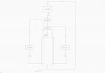
The system was designed around a 2 loop calorifier freshwater storage tank. It uses two thermostats and a couple of thermal switches for safety and control.

Domestic hot water heating is the core of the system. The first thermostat monitors tank temp and controls the boiler to maintain that temp(125F), cycling boiler and pump as needed. There are 2 thermal snap switches that will disable the heat source if the tank gets overheated. The flow out of the boiler passes thru 2 heat exchangers to reach the tank. this is all your domestic freshwater. As you draw hot water from the tank the water system replaces it and the thermostat fires the boiler as necessary to maintain set temp.

The second thermostat controls your room heat. When it calls for heat it turns on the heat system circ pump. This pushes fluid thru the loop in the tank collecting heat from there, and on thru a heat exchanger then on to the heater fan/coil unit or hydronic floor loop to deliver heat to the room. When the tank temp drops, the 1st thermostat calls the boiler and sends heat Into the tank. The heat exchanger picks this heat off and sends it to the room until the 2nd thermostat is satisfied with room heat and shuts off its pump. When the tank warms, the 1st thermostat shuts off the boiler…

A thermal switch on the engine shifts the control of the 1st thermostat from boiler and pump, to just pump and engine loop pump. So if the engine is warmer than say 120F if the tank thermostat calls for heat, the boiler pump and engine pump will engage, engine heat will arrive at the first heatex and be transferred into the tank. Again the two thermal switches on the tank will disable the boiler pump and engine pump if the thermostat should stick and the tank become overheated. When the tank is at set temp the thermostat shuts off the pumps. If you have room heat turned on when the 2nd thermostat calls for heat it works the same way except the 1st thermostat will call on the engine for heat if it is over 120F… When you shutdown and the engine cools below 120F, the system will automatically revert to boiler mode.

Engine pre-heating works exactly the same as habitat heating. You turn on a switch which energizes the engine pump. It pushes water thru the tank loop to absorb heat then thru a heat exchanger and on to the engine Warming the block and head. As the tank temp drops the 1st thermostat calls on the boiler which pushes heat thru that heat exchanger so the engine, like the habitat heat, gets first crack at the good stuff out of the boiler… you could put a thermostat on it, or a simple timer, or disable that manual control when you turn on the vehicle ignition, however you see fit.

the core is your fresh water system, both loops for habitat heat and engine heat would be a glycol solution. The drawing does not show any expansion tanks for dealing with thermal expansion so that is also needed…

FYI
IMG_4089.jpeg
 
Top