• Steel Soldiers now has a few new forums, read more about it at: New Munitions Forums!

  • Microsoft MSN, Live, Hotmail, Outlook email users may not be receiving emails. We are working to resolve this issue. Please add support@steelsoldiers.com to your trusted contacts.


MEP-004a Generator runs but shuts down no fuel pumps run

CUCV_ut

Member
89
10
8
Location
Ogden, UT
Hello

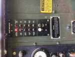
I was checking out my MEP-004a generator and it started right up but then dies. I noticed the low fuel light came on and it ran for a couple more minutes with the battle short switch on.
20191104_113518.jpg 20191104_113529.jpg
20191104_113725.jpg
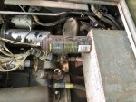
I had been reading up on the mep-004a threads and had a few ideas of what to check. The main fuel tank had 7 gallons of fuel in it, about 1/2 full according the TM. Next I found the day tank mounted right above the two fuel pumps. I unscrewed the infamous float switch to check it and found the day tank empty. That's when it occurred to me that I hadn't heard the fuel pumps come on. When I lift either of the two floats I hear a relay click. I will call the float switch good for now and moved on to the fuel pumps. I powered the front one up manually and it sounded good, when I lowered the top float the valve by the day tank clicked and fuel started filling the tank. That's another good sign the float switch might be good.
20200307_143148.jpg 20200307_114033.jpg 20200307_145614.jpg
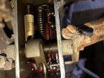
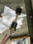
I checked the wiring harness for both fuel pumps and never got 24v when the generator was set to run, battle short, top float up. Next I wondered if the rear pump works. I jumped it to 24v and got a huge spark, almost like it was shorted out. I imagine it must be stuck. My theory is this pump went bad and fried something. Anyone seen this before? I wonder if something in the big relay box got burnt. There's a small relay mounted on the day tank that I think runs the fuel valve next to the tank. Does that sound right?
20200307_143156.jpg
Am I correct that the fuel valve is open (on) any time the fuel pumps are running? I wonder if I could install another relay using the same signal to switch the fuel pumps on. Here's a few pictures of the MEP-004a for reference.
20200307_145554.jpg 20200307_145550.jpg 20200307_111728.jpg
I've tried searching some old threads, but lately I keep getting an error that some search strings were too short and it ignores them. For example mep-004a I think it counts the - as a space and figures mep and 004a are too short. Is that happening to anyone else? I appreciate anyone's experience or suggestions on this. I'd like to get it running, as you can see it is in pretty clean shape other it doesn't run :). I guess you'd call it ran when parked. I just picked up an FDECU-4 this week and have heard this is the smallest generator that will power those, so I'd like to get it running right again. Also, a big thanks to everyone that has provided great advice and assistance in the past on my various projects.
 

Scoobyshep

Well-known member
914
989
93
Location
Florida
Theres a rectifier up there thats functioning as a diode block. Personally i had one there the check valve in the pump jammed up. I had to unscrew the bottom of the pump and knock the ball loose.

Switch in run and battle short on you should hear the pumps running, fast if day is empty real slow if its full (thats from pressure and not a float)

Sent from my SM-G950U using Tapatalk
 

CUCV_ut

Member
89
10
8
Location
Ogden, UT
I know how everyone likes details, so I'll post up some measurements I took. At the connector that plugs into the float switch I have 25 volts on pins A and C. On pin D I have 338 ohms to ground. On pin B I have around 300k to 8.5 Mohms.
20200307_145601.jpg 20200307_114038.jpg
On the sensor itself, I noted the pins C to D appear to be the bottom float. Up is open and down is 0 Ohms. Pins A and B appear to be the top float. with the float up it is an open connection, with it down it is 0 Ohms.
 

Guyfang

Moderator
Staff member
Moderator
15,866
22,086
113
Location
Burgkunstadt, Germany
Lets start with some basics. Normally, when the gen set is running, powered up, or when the S2 is in the run position, (engine not running) with the S7 in the emergency by pass mode, the electric fuel pumps, (B2 and B3) will run ALL THE TIME. They never shut off. So why do you sometimes not hear them? Or they are running real slow, almost unable to be heard? That's the function of the FL1 and FL2 switch in the day tank. When the day tank is full, the FL2 part of the float, tells the L2, (day tank solenoid) to shut. When the solenoid shuts, the fuel being pumped by B2 and B3 can not go any place. The fuel system is full and closed off. So the pumps "stop" pumping.

The first thing you need to do is get out the books. There is a troubleshooting procedure to follow. To get started, remove the fuel pump that gave you a big spark. open it up. remove the bottom and filter. Soak it in something to remove the varnish/lacquer from the inside of the pump. Or at least try this. It may be that you simply have a bad pump. AND, the pump that is not working. Is it the second pump? The last pump in the fuel system? There are pumps, and there are pumps. This system was designed to run on one pump, if it has to. If one pump fails, the other pump should be able to suck or pump fuel through the defective pump. Not all the fuel pumps will do that. They look all the same, but are not. You have to look at the part number on the pump. If you can get the pump to work, hook it back up. There are some "star´washers" that are supposed to be used to give the mounting bolts a better grounding for the pumps. If you do not have them it should still get ground, but sometimes its not a real good ground. If your second pump will not work, simply hook the input and out put hoses to the one pump that will work, and that's good enough for now.

Open up the TM9-6115-464-12, to page (PDF reader page #) 143. This is the procedure for testing the FL1 and FL2 switch. Read it, and do it. Right after you get finished, read some more, and test the L2, (solenoid) and the CR27 blocking diode, (what you thought was a relay). Check all this out, its easy and will not take you long.

If all this is good, open the Special Relay box, and look at the A5 circuit card. remove the mounting nuts and look at front and back of the card for burn marks.

Thats your job for now. Tell us what you find.
 

rorub

Member
38
21
8
Location
VA
Did the OP ever get this working? I tested my recently acquired 004 and I'm having similar issues.

I tested the FL1 and FL2. A to B fails and B to C fails. There is continuity between A to C.

I tested the rectifier and from Red to either Yellow 79.3 ohms and when I reverse polarities I get 126.3 ohms and 79 ohms. Has anyone sourced a replacement rectifier locally (Napa)? Prior to testing and reading the TM, I manually filled the day tank to see if I could get fuel to the IP.

I do hear a click when I use the battle short switch.
 

Scoobyshep

Well-known member
914
989
93
Location
Florida
Did the OP ever get this working? I tested my recently acquired 004 and I'm having similar issues.

I tested the FL1 and FL2. A to B fails and B to C fails. There is continuity between A to C.

I tested the rectifier and from Red to either Yellow 79.3 ohms and when I reverse polarities I get 126.3 ohms and 79 ohms. Has anyone sourced a replacement rectifier locally (Napa)? Prior to testing and reading the TM, I manually filled the day tank to see if I could get fuel to the IP.

I do hear a click when I use the battle short switch.
Try testing it with the diode selection on your meter. As for a replacement virtually any bridge rectifier will do.

Sent from my SM-G973U using Tapatalk
 

rorub

Member
38
21
8
Location
VA
Thanks, readings are still not correct per TM. I’ll look I for a bridge rectifier locally. Trying to see if I can start it with the day tank manually filled.
 

Guyfang

Moderator
Staff member
Moderator
15,866
22,086
113
Location
Burgkunstadt, Germany
Once there is fuel in the day tank, the set should start, IF, The S2 works, the S9-3 works and the L1, engine fuel solenoid works. You need to look at the wire diagrams.

1621281619315.png
 

rorub

Member
38
21
8
Location
VA
Thanks, I was looking at that and trying to understand how it all works.

S9-3. Trip - 1200-1250 rpm. Reset-Manual - I'll search the TM to see how to test this.

L1 - engine fuel solenoid - If this is the one on top of the IP, I was getting around 18V when cranking. Ray suggested I try to move the lever slightly clockwise and apply 24v to the solenoid to see if I could feel it tap the lever. I could feel it tap, but I'm new to this so I might not know exactly what I'm supposed to look for.

Fuel did pour out when I opened the timing cover. I will try and take off the lid off to see if there is fuel in there. I need to reread and review the exploded view.
 

Guyfang

Moderator
Staff member
Moderator
15,866
22,086
113
Location
Burgkunstadt, Germany
Thanks, I was looking at that and trying to understand how it all works.

S9-3. Trip - 1200-1250 rpm. Reset-Manual - I'll search the TM to see how to test this. Normally, if the S9 is tripped, you get what we call an "idiot light" on the fault indicator. The reset switch on the fault indicator ONLY resets the light. The S9 reset switch is on the S9. To see if the S9-3 is working, take a paper clip and stick it in Sp, J37, pins A & B. This will let the starter turn over the engine. Then have someone else try and start the set with S2, and you measure for 24 volts on pin J27-C. Yes, its kinda a fumble. But its the only way to TEST the S9-3. There are severl places easyer tto check it, but then you do not really know if its S9-3, or a wire/connection in between. You can measure at L1. But there again, is the problem the S9. or the 2-3 cannon plugs and TB's in between.

L1 - engine fuel solenoid - If this is the one on top of the IP, Yes. Its that one. Its passable to test/feel if the L1 is activating. Have someone place the S2 in the run position, and the S7 in the up position. If everything is good in the circuit, you can feel/hear the click at the L1. I normally just check at wire P80N on the L1. Its the hot wire. You can take two wires and go from the battery's, and jump the L1. Pos to P80N wire, and Neg to P55X. Do this test with everything shut off. I was getting around 18V when cranking. Are your battery's tip, top, charged? Ray suggested I try to move the lever slightly clockwise and apply 24v to the solenoid to see if I could feel it tap the lever. Correct, and a good way to see if the lever moves. But keep in mind, a click or clack is NOT always a sign it works. But it means at least you are getting VDC to the right places. I could feel it tap, but I'm new to this so I might not know exactly what I'm supposed to look for.

Fuel did pour out when I opened the timing cover. I will try and take off the lid off to see if there is fuel in there. I need to reread and review the exploded view. If you had fuel coming out the timing cover, you have fuel above. And I would say that you are getting fuel to the IP.
Open to read comments
 

rorub

Member
38
21
8
Location
VA
Okay, I'll look at the diagram and follow the test you have outlined. The only light I have is the low oil pressure which I’ve read was normal.

I set my meter up so I could read the voltage when cranking. Didn’t have my alligator clips, so I just stuck them under the wires. It was reading 18V to L1. One thing I failed to mention is I’m using the batteries connected to my 003 via 6awg jumper cables. The engine cranks fine, but maybe I’m getting too much of a voltage drop to L1?

I should just make a new terminal so I can connect the batteries directly to my 004. I was just excited to see if I could get it to run after I did a quick run through of everything (picked up the genset yesterday).

I was definitely getting a click and clack. Wasn’t a strong push and I don’t think it would have pushed the lever all the way back to the left.

The day tank was bone dry when I tested the float switch per your instructions in another thread. I didn’t have another person, but I’m pretty sure I did it correctly. After testing that and rectifier I decided to just fill then day tank manually. It was bone dry, but after waiting for a little I was able to get fuel to the IP.

Hopefully, I find the issue after testing per your instructions and I don’t have to rebuild the IP.
 

rorub

Member
38
21
8
Location
VA
Since I didn’t have a helper I continued troubleshooting the IP. It appears to be locked up. There is a lot of resistance to move things around.

Also, I guess someone used a can of ether. The fuel cutoff solenoid does work when I jumped it.

I also put 24v to the fuel rectifier and it does trigger the fuel solenoid on the day tank. Pumps still didn’t pump.
 

Attachments

Guyfang

Moderator
Staff member
Moderator
15,866
22,086
113
Location
Burgkunstadt, Germany
Think now. What controls the E1 and E2 pumps. The FL1/FL2 float switch. Look at the attached wire diagram. Look for FL2. Put the set in the run position. Flip up S7. Go to the J33, (day tank float C-plug. Mesure from ground to J33-A. Do you have 24VDC? If so, pop the CB1, insert a paper clip in J33-A and J33-B. Do the pumps come on?
 

Attachments

rorub

Member
38
21
8
Location
VA
Thanks for this, I plan to test when I get a second. I purchased my first diesel (DJE light tower) in September. I'm learning as much as I can. I purchased my 003s shorty after and I'm starting to get the hang of reading the TMs.
 

rorub

Member
38
21
8
Location
VA
Think now. What controls the E1 and E2 pumps. The FL1/FL2 float switch. Look at the attached wire diagram. Look for FL2. Put the set in the run position. Flip up S7. Go to the J33, (day tank float C-plug. Mesure from ground to J33-A. Do you have 24VDC? If so, pop the CB1, insert a paper clip in J33-A and J33-B. Do the pumps come on?
Nothing from J33-A to ground. I did pop CB1 at the panel and jumped A-B just to check
 

rorub

Member
38
21
8
Location
VA
I figured you meant to add that, but yes I did CB1 back on and the pumps aren’t running. I left the speed switch disconnected and that did not let me crank the engine.

Letting fuel sit in the day tank overnight has allowed me to see the fuel lines leaking. I’ll get those replaced soon.
 

rorub

Member
38
21
8
Location
VA
I apologize, my analysis was not clear on that status of my 004. Here is where I'm at:

  • Fuel rectifier appears to be defective - when 24v is applied, fuel solenoid has a loud audible click, but pumps do not come on.
  • Pumps do not run with S2 and S7
  • Fuel shutoff solenoid works properly when 24V applied, while engine is cranking I see around 18V. I don't have alligator clips on the terminals so it might not be an accurate reading (testing solo).
  • Manually filled day tank, but unable to get fuel to injectors. Opened top cover of IP and linked moves with some resistance, but 45. Lever, throttle level does not move. 35. Lever, throttle does not move 45 neither. I ordered a rebuild kit for the IP, but not positive I will tackle this myself
  • Accidentally left my speed switch disconnected and tried to crank engine over with S2. Engine would not crank which leads me to believe the overspeed switch is working?
  • Fuel gauge does not work. Initially it was on E after cranking it is now stuck past F
  • Oil pressure gauge does not build pressure when cranking. I tried to find out if this is normal in the TM.
I'm trying to determine the best way to apply 24v to fuel pumps to test them. Currently plan is to properly remove the IP, replace leaking fuel lines and determine why my pumps aren't running. I appreciate all the suggestions and assistance.
 

Guyfang

Moderator
Staff member
Moderator
15,866
22,086
113
Location
Burgkunstadt, Germany
I apologize, my analysis was not clear on that status of my 004. Here is where I'm at:

  • Fuel rectifier appears to be defective - when 24v is applied, fuel solenoid has a loud audible click, but pumps do not come on. (Don't be so hasty. TEST, TEST and more TEST.)
  • Pumps do not run with S2 and S7
  • Fuel shutoff solenoid works properly when 24V applied, while engine is cranking I see around 18V. I don't have alligator clips on the terminals so it might not be an accurate reading (testing solo).
  • Manually filled day tank, but unable to get fuel to injectors. Opened top cover of IP and linked moves with some resistance, but 45. Lever, throttle level does not move. 35. Lever, throttle does not move 45 neither. I ordered a rebuild kit for the IP, but not positive I will tackle this myself. (Do read the -34 TM before working on the IP. If you get a shop to do it, tell them that this is NOT a normal IP. Yes it looks like a run of the mill Roosamaster, but it set up a tad different, and it should be adjusted IAW the TM. Ray can help you with this. He has done it of late. )
  • Accidentally left my speed switch disconnected and tried to crank engine over with S2. Engine would not crank which leads me to believe the overspeed switch is working? (At least S9-1 contacts)
  • Fuel gauge does not work. Initially it was on E after cranking it is now stuck past F (check the wiring. check the grounds)
  • Oil pressure gauge does not build pressure when cranking. I tried to find out if this is normal in the TM. (It should)
I'm trying to determine the best way to apply 24v to fuel pumps to test them. (Unplug the wires to the two pumps. Remove the fuel line from the last pump, at the Day tank Solenoid. Put the end of the fuel line on a bucket. Take a short piece of wire and go from the big lug on the starter, Pos, and touch the wire to each pump wire. They should both pump fuel into the bucket.) Currently plan is to properly remove the IP, replace leaking fuel lines and determine why my pumps aren't running. I appreciate all the suggestions and assistance.
Open to see comments.
 
Top
AdBlock Detected

We get it, advertisements are annoying!

Sure, ad-blocking software does a great job at blocking ads, but it also blocks useful features of our website like our supporting vendors. Their ads help keep Steel Soldiers going. Please consider disabling your ad blockers for the site. Thanks!

I've Disabled AdBlock
No Thanks