-
Steel Soldiers now has a few new forums, read more about it at: New Munitions Forums!

Newbie checking out a deuce today??
- Thread starter andytk5
- Start date

More options
Who Replied?Horst
Member
- 54
- 12
- 8
- Location
- Munich, Germany
Now certainly you will. You need to remove the HH again. Make sure that the plunger button is there. Turn the engine until you have #1 cylinder in compression, align the damper marking and install the HH. Now the notch has to align with a valley right next to the scribed tooth. The scribed tooth will be to the right of the notch. Hopefully Gimpy reads this and checks for correctness. I learned this from him.
Last edited:
GREAT! Super excited about being an idiot..Now certainly you will. You need to remove the HH again. Make sure that the plunger button is there. Turn the engine until you have #1 cylinder in compression, align the damper marking and install the HH. Now the notch has to align with a valley right next to the scribed tooth. The scribed tooth will be to the right of the notch. Hopefully Gimpy reads this and checks for correctness. I learned this from him.
 Well at least I will KNOW my engine is setup correctly. I will peruse some TMs about the timing also since it is HOT at the moment. Thanks again for the advice Horst.
On a side note that Apple Rubber Co. sent some fine looking viton orings. I have 2 more sets to last the life of this truck.
Strange thing now is I have the tooth lined up with the pointer and I can't get the HH out.. I have tried a little before and a little after the mark and no dice..
I gotta give my back a break so I'll try later.
As per TM9-2815-210-34-2-2 we had it set with the pointer at the tooth just to the left of the red tooth(red tooth one to the right of pointer) and still won't come out. It will twist and turn both ways but not out. When I took it out it just came out. Grr..
I have it super loose and it has allot of slop in it now and I am able to wiggle it and move it up and down a 1/16" but just won't come out. I really have no clue at this point, stuck here for the past 2 days..
Last edited:
Finally got it out after continously turning it and trying. Thanks alot to Chris (gimpyrob) for the help! Gonna tme it up tommorow.
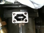
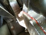
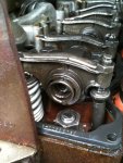
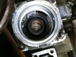
Getting ready to reinstall the HH. The front piston rockers are flat and are loose, one more than the other. Also all the lines are matched up perfectly. Some pics for reference.
Problem is once i get the timing marks lined up the gear inside the pump housing is partially covered not letting the HH gear seat. Now if I move the engine so the gear is exposed then the marks are off.
Edit: looks like I mixed up the #1 and #2 lines on the HH so when I started it, it smoked and idled at 8-900 and sounded generally like ****. My friend greg called and told me how his lines were set and mine were wrong.. Duh..
Attachments
-
 54.4 KB Views: 26
 -
 66.5 KB Views: 26
 -
 76.5 KB Views: 26
 -
 67.4 KB Views: 27
Last edited:
So the HH issue is over..
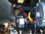
On to the 12V stuff. Have the bracket and alt all bolted in, everything is wired just not connected or energized.
Question 1: Since it was siad I can use the same ground between the 12/24V systems can I do it using these methods in the pics. The 12V alt ground is jumped onto the 24V alt ground tab since the wire runs down to a ground point. That ok?
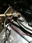
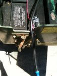
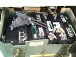
Question 2: Similar idea in the batt box (2nd picture) tieing the 12V batt to the 24V batt ground wire that runs to the chassis. Doable?
The small red and larger black wires (3rd pic) are the + switched and alt charge wires.
The 12V alt will be turned on with a dash mounted switch for the time being since I had all this stuff. I have a 6 tab fused buss mounting to the firewall that will be supplied by the batt with 8ga cables.
On to the 12V stuff. Have the bracket and alt all bolted in, everything is wired just not connected or energized.
Question 1: Since it was siad I can use the same ground between the 12/24V systems can I do it using these methods in the pics. The 12V alt ground is jumped onto the 24V alt ground tab since the wire runs down to a ground point. That ok?
Question 2: Similar idea in the batt box (2nd picture) tieing the 12V batt to the 24V batt ground wire that runs to the chassis. Doable?
The small red and larger black wires (3rd pic) are the + switched and alt charge wires.
The 12V alt will be turned on with a dash mounted switch for the time being since I had all this stuff. I have a 6 tab fused buss mounting to the firewall that will be supplied by the batt with 8ga cables.
Attachments
-
 72.7 KB Views: 22
 -
 79.7 KB Views: 22
 -
 69.5 KB Views: 21
 -
 25.6 KB Views: 19
Horst
Member
- 54
- 12
- 8
- Location
- Munich, Germany
ground is ground, no matter 12 or 24 volts. So that's fine. what do you mean by switching the alternator on and off? How do you want to do that?
Roger on the ground issue.
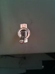
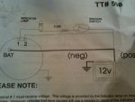
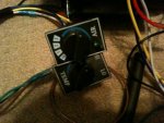
I should have made that clearer on the switch. Instead of using the relay and ignition switch to activate the alternator as the instructions said I was just using a simple on/off switch to send 12V to the alt. I posted a pic of what the directions were saying. Is that a safe way of doing it?
I should have made that clearer on the switch. Instead of using the relay and ignition switch to activate the alternator as the instructions said I was just using a simple on/off switch to send 12V to the alt. I posted a pic of what the directions were saying. Is that a safe way of doing it?
Attachments
-
 52.2 KB Views: 9
Horst
Member
- 54
- 12
- 8
- Location
- Munich, Germany
still not exactly understand. There is no relay in the drawing. But more important, I cannot see in your pic of the installed alternator that you connected the terminal 1 + 2. I just see a thin red wire in parallel to the positive wire to the battery.
I was going to use a relay that was activated by the deuce ignition switch, that would in turn send the 12V to the alt. Instead of doing that I am just suing a sep switch so no relay is being used.
Sorry about the pic but the 1-2 terminal area is on the bottom. The 2 red wires going under the alt are going to the 1-2 terminals. the #2 terminal needs constant power from the batt so I figured I would just jump it off the positive terminal on the alternator since the large black wire is coming from the positive of the battery instead of running a additional wire, seemed redundant.
So the #2 is getting power off that black positive battery cable thru the small red wire.
The #1 terminal is going from the alt to the dash switch then down to the pos batt terminal. The instructions say it needs voltage. This usually gets power from the ignition being on or off and I am just doing that manually by the dash switch.
Page 7 post #65 has pictures of the 1-2 terminals that are now under the alt in the pic.
Last edited:
Well I fired it up, turned on the switch and everything seemed to work great. Got 12+V at my buss. Before I ran anything I checked the 12V batt and had 12.4 V then when everything was running the Alt is putting out 14+ V. Seems like it's all good. Thanks for the help guys!
loxahatcheeman
Member
- 35
- 0
- 6
- Location
- Loxahatchee, FL
Maybe I missed it along the way, but did you add a sep battey for your 12v stuff. If so, where did you locate it? Is it better to do a dedicated 12v system? Or can you add a simple step-down converter? I guess it would depend on how much stuff you are running on the 12v...
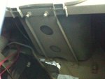
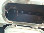
Yeah I have a third battery in the battery box. I cut the bumps down in the floor of the box and turned all my batts sideways so three fit side by side. I chose a seperate 12V system since I will prob be adding a good bit of 12V stuff. A converter will do just about anything that most will need. This was more of a preference than a any greater benefit.Maybe I missed it along the way, but did you add a sep battey for your 12v stuff. If so, where did you locate it? Is it better to do a dedicated 12v system? Or can you add a simple step-down converter? I guess it would depend on how much stuff you are running on the 12v...
Here's a better pic of the box.
Attachments
-
 75.8 KB Views: 31
I'll prob start a new thread just for the A/C part of my build once I am done so everybody can see the whole install in one shot.
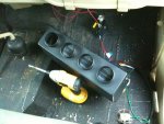
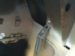
I have the evap box temporarily connected to the buss to make sure it works, go to go. I am planning to remove the inside of the glove box leaving the door in place. This will free up all that under dash space to tuck to evap box under the dash and route the flexible ducts to either side. It should look pretty neat after its done. I'll put the controls in the dash as well.
I am still fabbing brackets for a different compressor mount on the motor that I haven't seen used yet. Should be fun.
Attachments
-
 62.6 KB Views: 9
 -
 70.5 KB Views: 8
 -
 66 KB Views: 8
 -
 57.7 KB Views: 9
Is the seller a member of SS? Where is the truck? I know of at least one person to stay away from down there. If you need help on the west coast of FLA send a PM to cessnatwin or pctrans. They may be able to provide info or help.
Can you PM me the name of the person to stay away from when buying MV's in FL because I bought my M109A3 down there and had some "issues" of things not being what they were supposed to be.
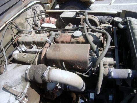
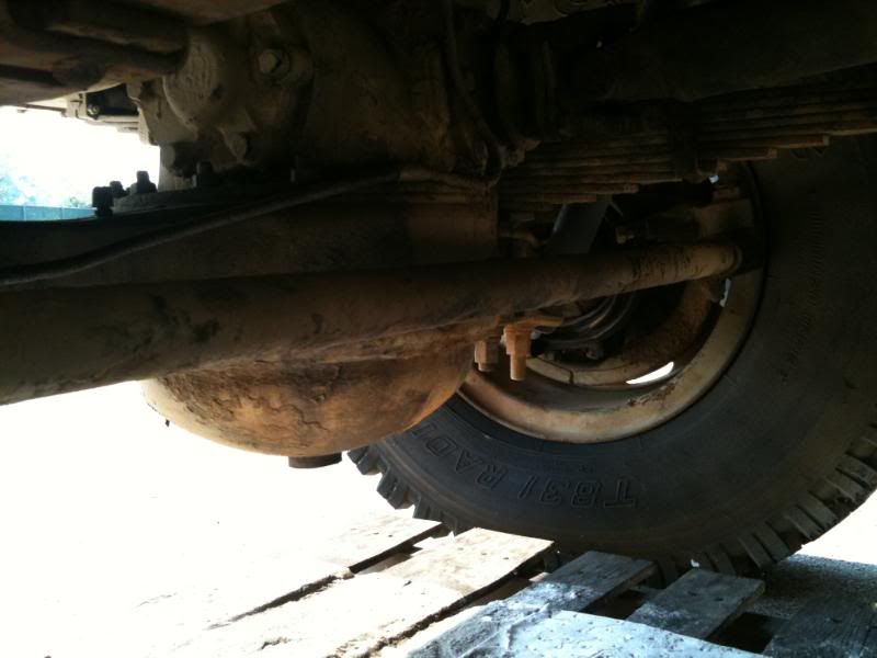
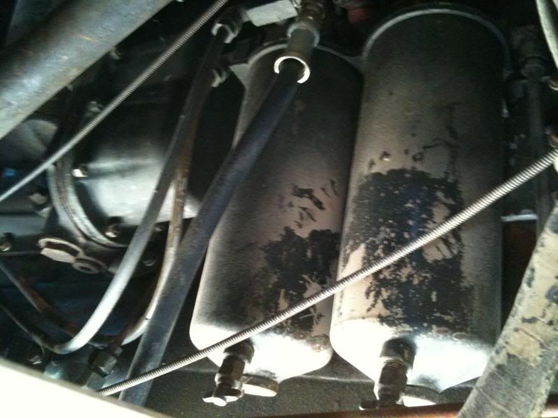
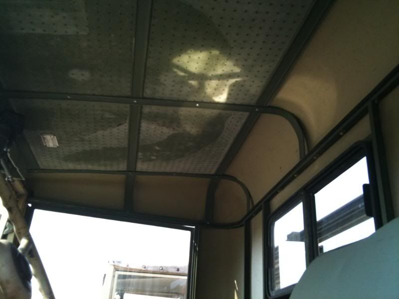
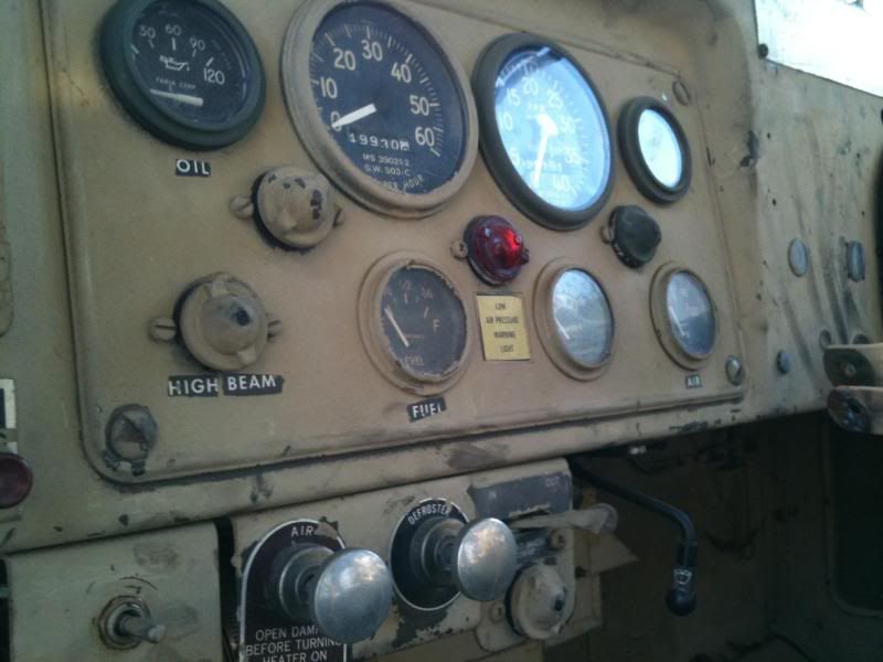
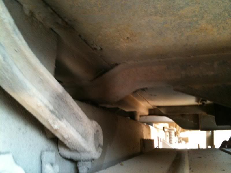
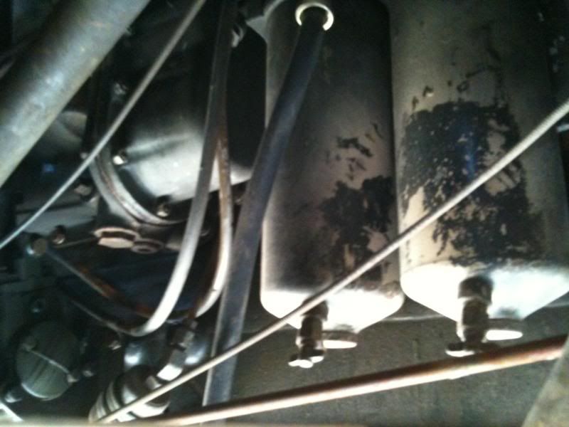
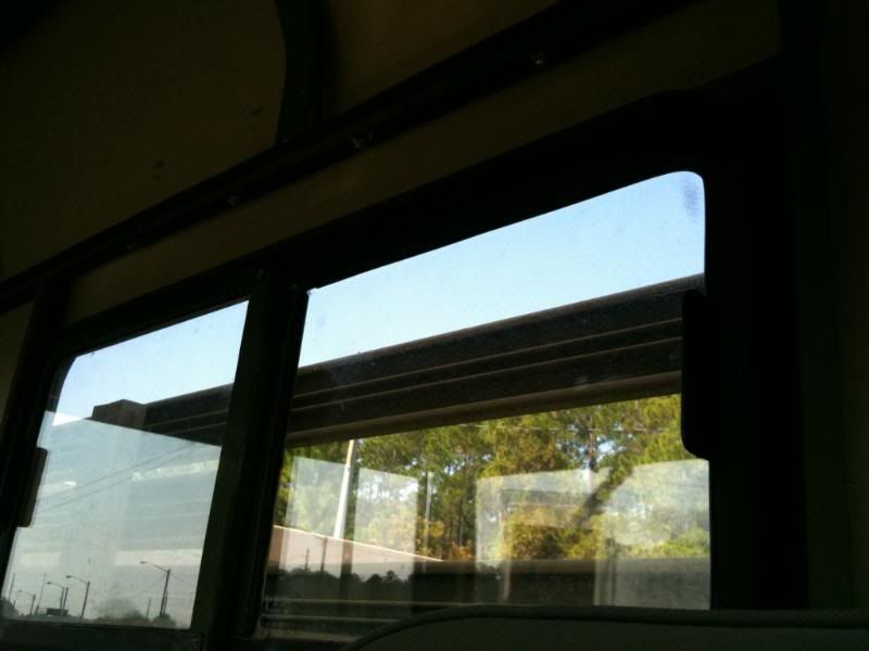
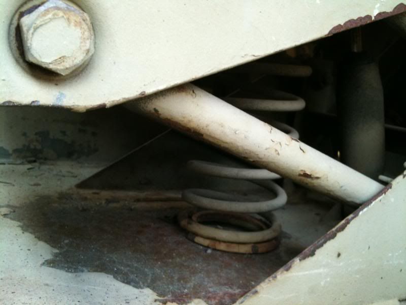
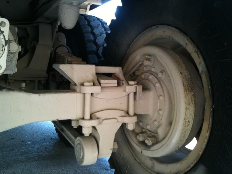
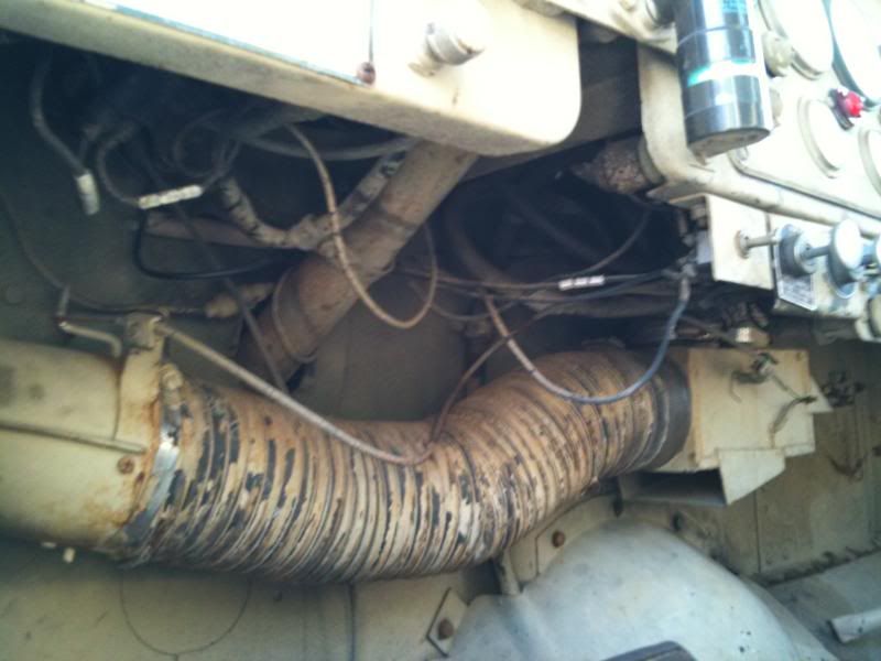
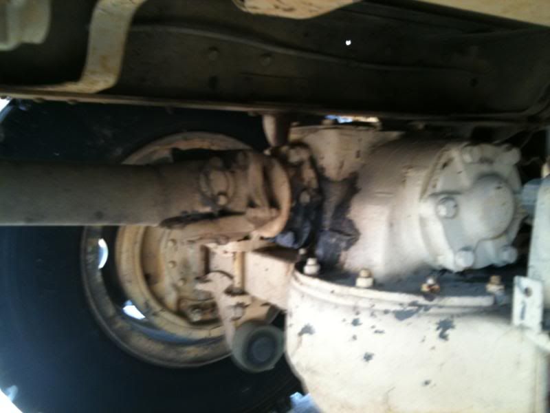
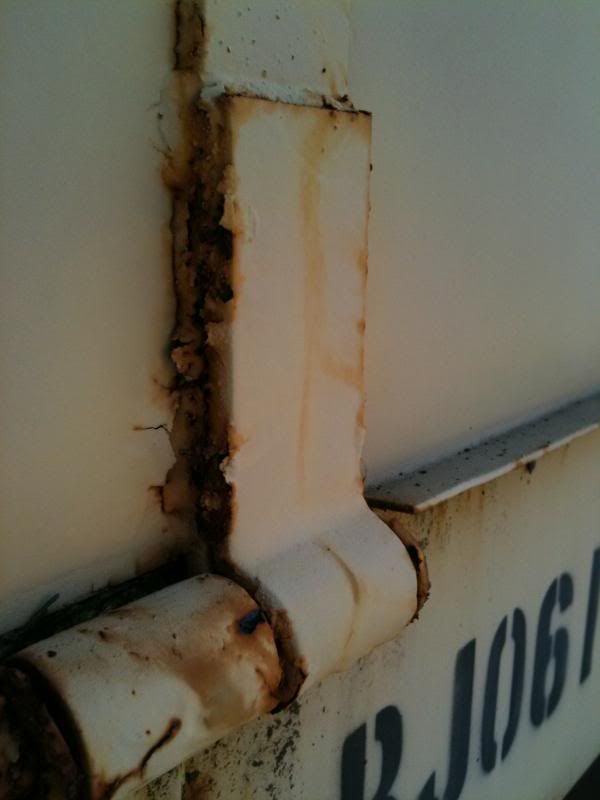
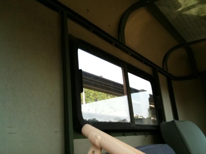
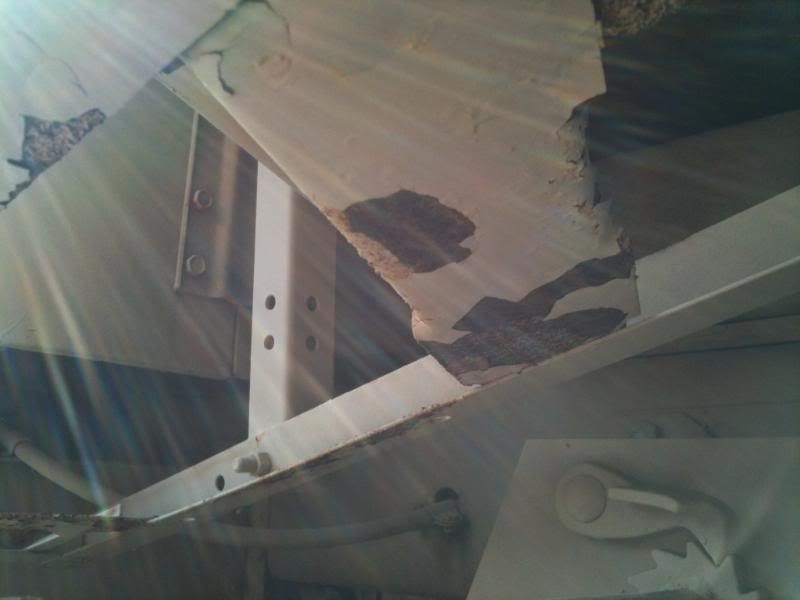
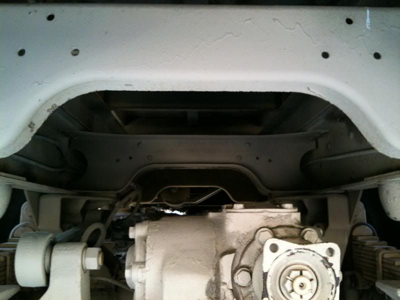
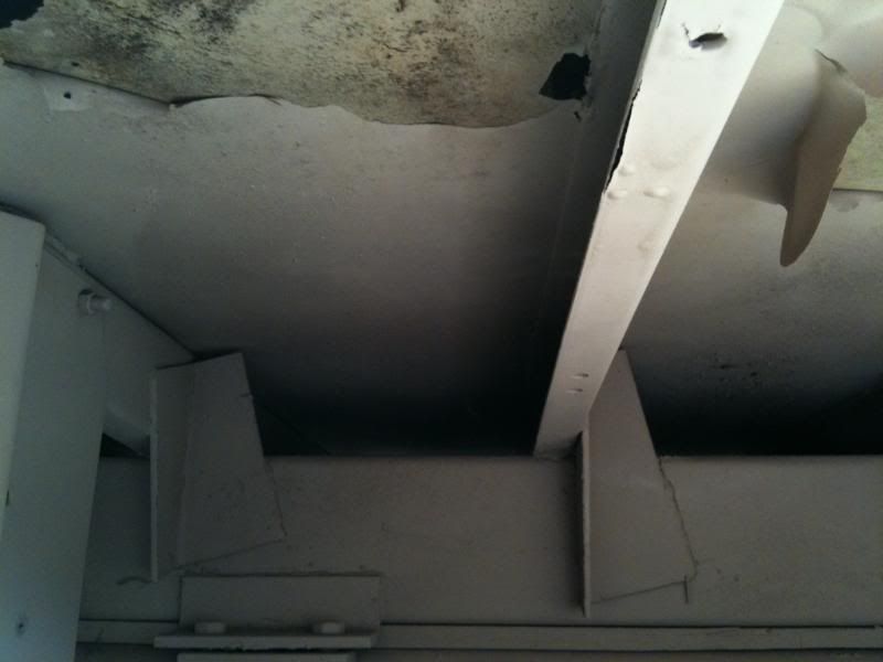
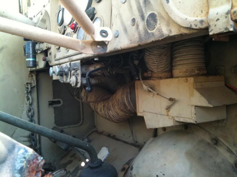
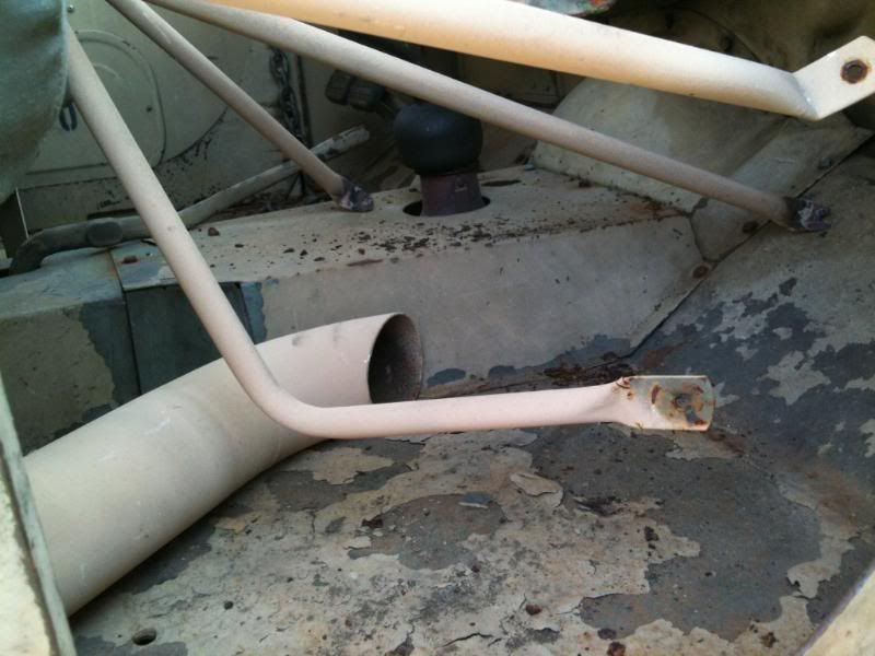
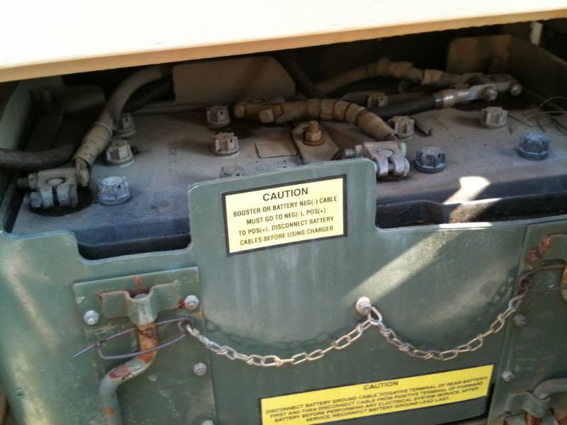
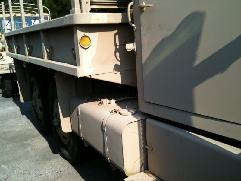
So here are some pics of the Deuce I won. Check out the crappy iphone pics and let me know if anything stands out that is FUBAR or a good ting. I know very little so just tell me what ya think.
Thanks
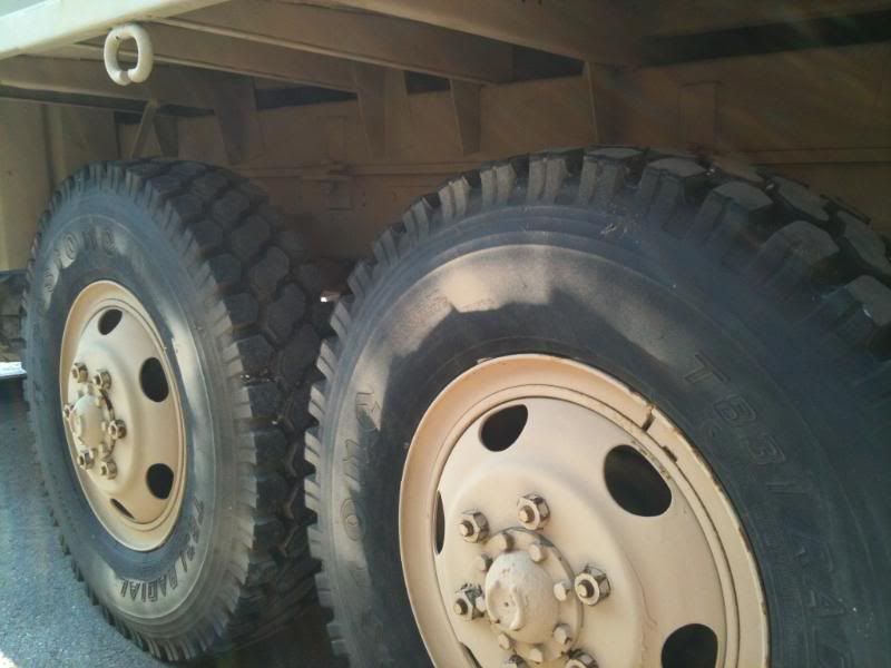
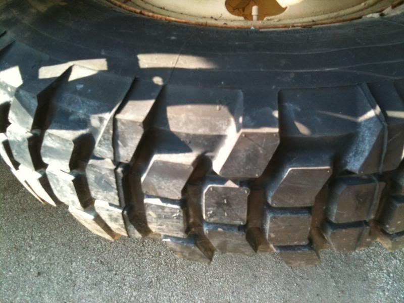
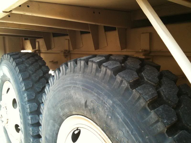
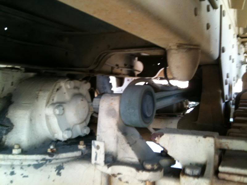
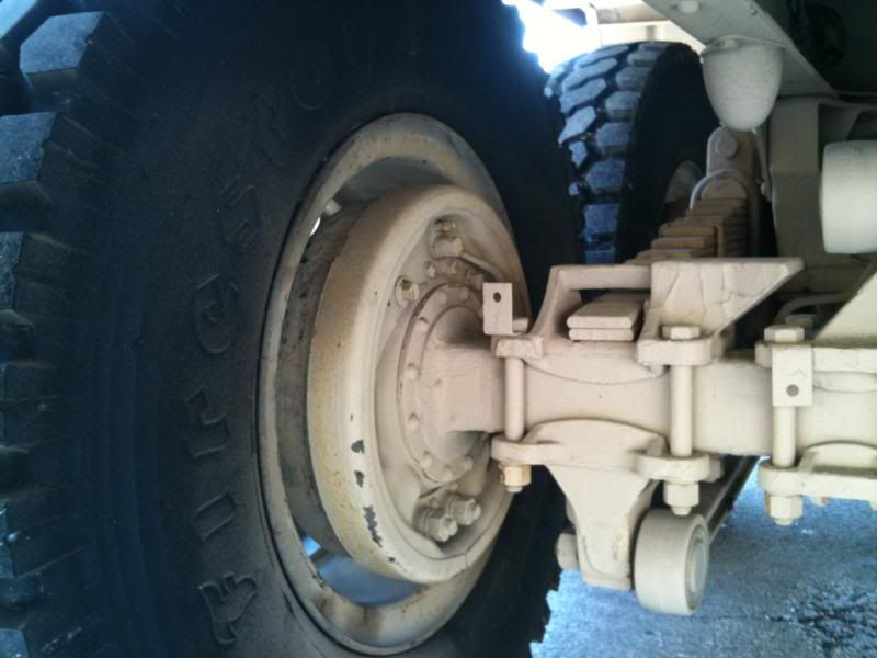
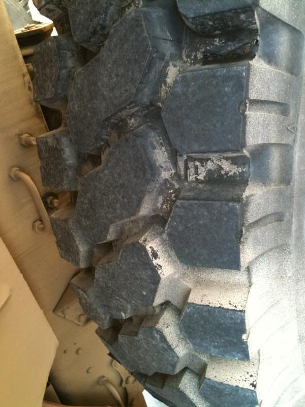
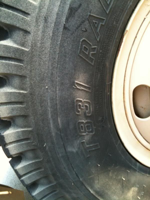
What size are the Firestone Tires are on this Deuce?
There are the 11.00x20 firestones somewhere areound 43"or so.What size are the Firestone Tires are on this Deuce?
I don't know who was to be avoided selling MV's here, somebody else may chime in on that one.
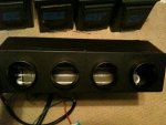
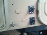
Here are some pics of the evaporator fan/box mounted behind the dash. I will be running some flexible ducting to the 4 under dash vents that will be installed later. Switches mounted in the dash for easy access. Fans blow pretty strong so with the refridgerant it will be nice and cool. Gotta measure for some hoses and weld my compressor bracket.
http://www.youtube.com/watch?v=6jAZrXmiets&feature=plcp
http://www.youtube.com/watch?v=6jAZrXmiets&feature=plcp
Attachments
-
 41.3 KB Views: 12
 -
 52.8 KB Views: 12
 -
 44.5 KB Views: 14
 -
 55.1 KB Views: 13
Last edited:
- 114,300members
- 167,187threads
- 2,353,746posts
- 3,753online users